


Wellington A Purdon recounts the construction of... Woodhead's first tunnel
Wellington A Purdon recounts the construction of… Woodhead’s first tunnel
Ventilation of works/drainage
Driving the headings/excavation & lining
Ventilation of works
It is known that in sinking a shaft vertically or driving a heading, either level or inclined to the horizon, a deficiency of pure air is felt after proceeding some distance, in consequence of the gases that are set free. It was therefore necessary, when driving the entrance stretches, to create a circulation to the face of the work, as it proceeded. This was contrived in the following manner. It has been stated, in describing the mode of construction, that two driftways were driven, one at the top and the other at the bottom of the tunnel. An air shaft 5 feet diameter was sunk on the centre line at a short distance from each entrance (before the thickness of the rock overlying the tunnel exceeded materially that at the face) until it reached the upper driftway of the tunnel. At the top of this shaft a furnace was constructed with a flue and chimney in continuation and, when the air at the furnace became rarefied by the heat, the denser air began to rush from the bottom of the shaft which caused a current from the face of the tunnel to pass through the upper driftway and air shaft to the furnace, and get off through the flue of the chimney. The open end of the upper driftway was then carefully closed up so as not to admit air and, from time to time as the work went on, at intervals of about 20 yards, a connection shaft 2½feet wide was driven between the two driftways, observing to close up carefully the last one whenever a fresh connection was formed near the working face.
A current from the entrance of the tunnel, through the bottom driftway, was thus made to circulate up to the face of the headings and returning by the upper drift and air shaft, passed out by the furnace in the way described. By this means pure air was maintained in the end stretches so far as there was occasion to drive, and it was thought possible to have driven much further in the same way.
This principle might have been employed in the stretches at the bottom of the various shafts, by applying a square pipe of wood (12 inches) up along the shaft side, from the upper driftway of the tunnel; and when it reached the top, an iron pipe of the same area could be added on and carried to the flue of the engine fire. This plan was not adopted as a system of blowing air into the headings, through pipes by a fan worked by the engine, was known to have acted successfully in other instances; although experience had not taught its effects in stretches so lengthened as those of this tunnel. It however served the purpose, only perhaps less effectually than might otherwise have been done.
The mode in which the air was forced down the shafts by the fan was through a square wooden 12 inch pipe which branched off into two others of the same description, directed towards opposite ends of the tunnel through the bottom driftway, up to near the face of the headings. A piece of pipe 12 feet long being added from time to time as the headings advanced.
Drainage
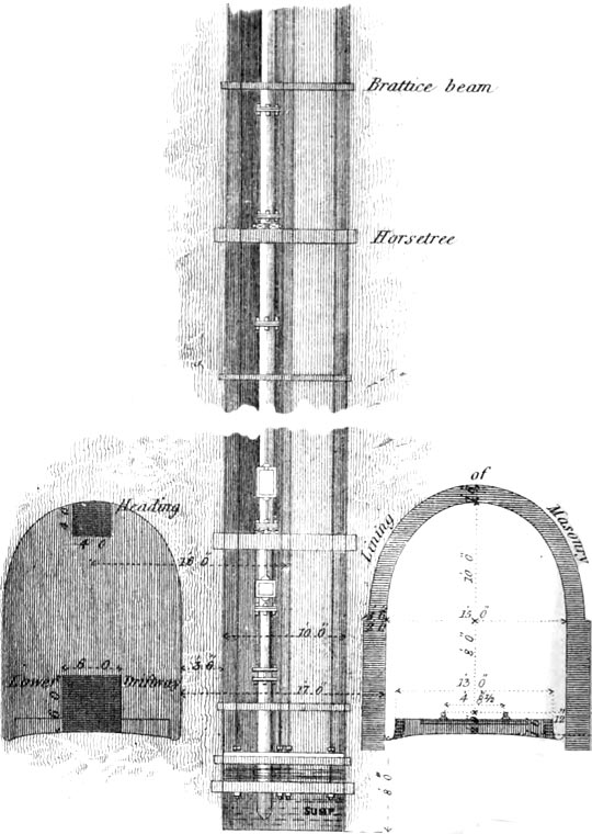
The drains for carrying off the water permanently were easily arranged, in consequence of their being an incline of one in two hundred throughout. It was only necessary to make a covered drain down the centre of the tunnel, or otherwise two side drains. The latter was preferred, and two open drains were provided (see diagram below) The size of the permanent drains was not of course determined until observation enabled a judgment to be formed as to the quantity of water after the mountain was thrilled.
Association attaches to a valley three miles long a considerable brook in the bottom and, in order to let as little water as possible pass down the tunnel, an outfall in the shape of a covered drain was carried up from a lower level in the valley at the eastern face until, by cutting 6 feet deep at the entrance, its bottom merged into the incline of the gradient at about 240 yards inside the face of the tunnel, from which point the water flows out at the eastern end. Towards the lower end of the tunnel, the quantity of water was of course greater and it was necessary to give increased dimensions to the side drains which was done by adding to the depth instead of increasing the width, owing to the confined limit for the ballast not conveniently admitting any other way.
It was not unreasonably imagined that, after the driftways were through, no further necessity should exist for drawing the water artificially from the workings. Such, however, was not the case except in the stretch from about 180 yards east of No.2 shaft to the western face. The water was not permitted to pass down the tunnel while the widening, excavation and lining were progressing because it interfered with the getting in of the foundation of the side walls and otherwise obstructed the proceedings, so that the water was drawn off by pumps to the latest period.
It is, however, right to state that had proper arrangements been made in time to obviate the inconvenience referred to, the water might have passed down without detriment during the operations.
The mode of permanent drainage having been stated, it remains to explain how the works were kept clear of water during the construction.
It is manifest, from what has been said, that in driving from the western face, the water had a natural outfall from the first. It was not so, however, at the eastern end, owing to the descent in the tunnel. An outfall was carried up, as before stated, which took back the water for 240 yards. Here it was necessary to sink a pump to a depth of about 3 feet below the plane of the formation and thence to carry on a drain from the bottom at a rise of about 1 in 600, the least inclination on which water was found to flow, until the bottom of this drain again met the plane of the gradient, when another sump of 3 feet was sunk, and so the operation was repeated. The water in each sump was raised by a hand pump to the adjoining higher drain and so passed to the outfall referred to. By this means, the descending stretches were drained at the eastern face and from the bottom of the various shafts, a main sump being first formed at each shaft, out of which the water was lifted in the manner that will be presently described. The water from the ascending headings naturally fell into the sump at the shaft’s bottom.
There was no point so difficult to form a judgment upon as fixing the power and appliances for drawing the water out of the shafts during the process of sinking and after they were got down. The amount of water to be met with was an unknown quantity; but, from the reasons mentioned at an early part of this paper, it was thought that pumps with working barrels, 8 inches diameter, which might be worked by the 25 horse winding engines, would be sufficient; accordingly this arrangement and power were provided and although it turned out defective in some respects, which occasioned delay and expense before exhausting the springs that were occasionally encountered, it answered the purpose except at No.2 shaft where it was found necessary to put in a double set of similar pumps and two engines to overcome the water that was met with. The extra space occupied by the pumps and timbers in No.2 shaft prevented any base larger than 4 feet 9 inches to be transferred through the shaft into the interior.
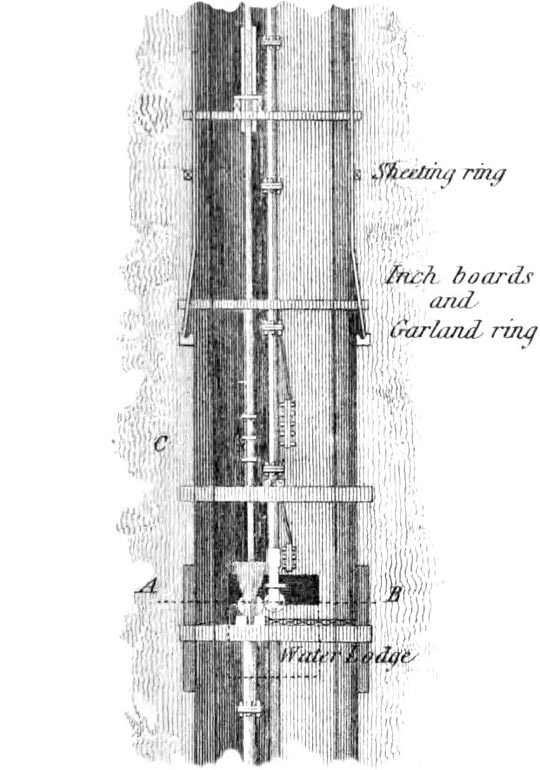
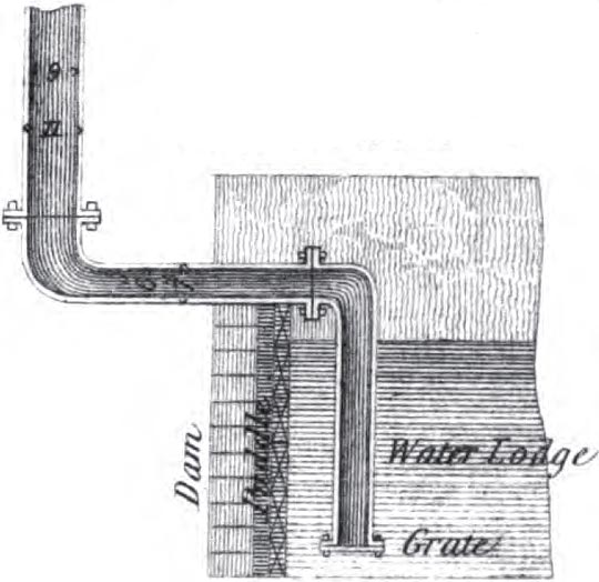
For the first 20 or 30 yards of the sinking, the water was raised in the usual way, by a water barrel of 100 gallons, and a driftway was driven at about this depth out from the shaft to the surface of the hillside to deliver the water that should be lifted from a greater depth when the pumps were introduced. The pumps occupied a segment of the shaft set apart for the purpose and were supported by flanges at the joints and the requisite horse-trees and collars etc (see two diagrams above and one below). The pump-trees were 9 inches diameter, in lengths of 9 feet, with a 10 inch wind bore and slide to adapt to the bottom as the sinking proceeded, and to admit from time to time another joint of the pump-trees to be added on. The wind bore was made very strong in order to withstand the blows it received from blasting in hard measures and the slide bore passed in through a packing box at the upper end and, being 10 feet long, permitted a variation of 9 or 10 feet in the depth from which it lifted so as to enable another 9 feet length of pump-trees to be added on as required.
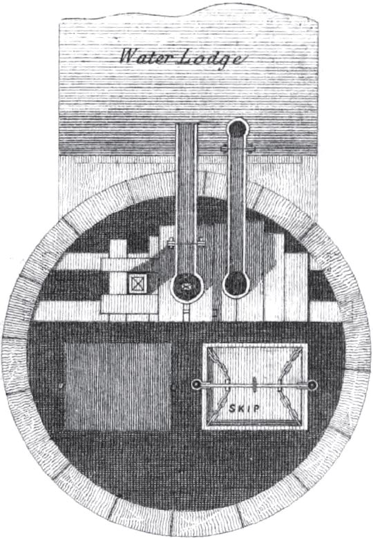
The vertical range of the shafts was divided into three separate lifts of pumps and, at the level where those lifts were broken (as it is termed), a chamber was excavated in at the side, 50x7x5 feet dimensions; and a puddled dam 4 feet high was raised abreast of it and flush with the lining of the shaft. This was capable of holding from 6,000-10,000 gallons of water. The higher lifts were proportionately longer than the lower ones in order to compensate for the greater weight and strain of pump rods necessary to reach to the lower lifts, from the L legs at the top of the shaft (which were worked by the engines in the manner shown below).
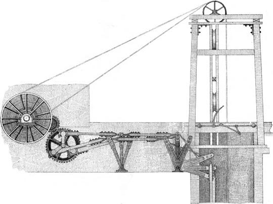
The lowest lift of pumps raised the water from the sump at the bottom of the shaft to the first lodge whence it was raised to the second lodge by the middle lift and thence, by the top lift, to the near surface and discharged through the drift already described.
Before dismissing the subject of drainage, it may be stated that the two more westerly shafts had considerably more water than those to the east side of the hill, arising probably from their position relative to the outcrop of the strata on the western escarpment and the beds of grit being more porous.
Ventilation of works/drainage
Driving the headings/excavation & lining