


Wellington A Purdon recounts the construction of... Woodhead's first tunnel
Wellington A Purdon recounts the construction of… Woodhead’s first tunnel
The range and levels
Driving the headings/excavation & lining
The range and levels
The setting out of the line of the shafts and transferring the range and levels into the interior of the hill was a practical performance of some nicety and consequence, which was entrusted to the author of this paper.
The two ends of the tunnel were determined by considerations relative to the approach of the railway and it was necessary, in the first instance, to connect the two points in question by a straight line passing across the summit ridge. This was readily affected by means of a theodolite. A line, starting from one of the points and directed towards the other, was carefully ranged and measured through a succession of station points (10 in number) situated in the line upon the most prominent features of the ridge. The distance from the beginning of the line to each station was noted, as well as the point at the end abreast of the other entrance. It was found that the line, thus set out, passed 92 feet wide of the required point. Then by similar triangles, as the extreme length of the line measured is to 92 feet, so is the distance up to each station to the length of lateral shift into the line required. A row of ranging rods were then placed in the points thus found and, by a few trials with a portable transit, were soon adjusted so nearly into a straight line that it was found afterwards, by more refined means, to be but two inches out.
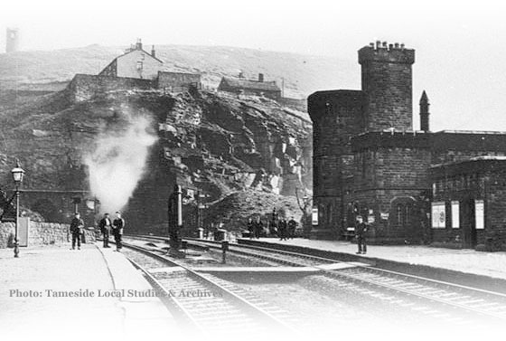
Upon the line thus set out, four observatories were erected (see above photo, top-left), between 30 and 40 feet high, one of which was at the summit point and the others at the leading points of the escarpments, by which means the whole range across the hill was observed and a view commanded of every shaft at no greater distance than half-a-mile from one or other of the observatories. These were round towers, 13 feet diameter, with a concentric pillar carried up within and a stone table placed on it for the transit to rest upon. There was a winding staircase leading up to the foot of the stone table, at which level a floor was placed. Neither the floor nor stairs were anywhere in contact with the centre pillar. The outer walls of the tower were carried up about 8 feet higher than the floor and the whole was covered in with a flat leaded roof, surmounted by a coped parapet. Windows opened upon the range of the tunnel in opposite directions; the chamber inside was protected from the high winds and the instrument freed from vibration.

There was a telegraphic arrangement attached to each tower, for indicating the movements required to be made for the adjustment of the necessary points upon the range.
Transits of 30 inches focal length and 2¾ inch object glasses, and stands with lateral slide motion, were applied upon the stone tables, and brought to bear upon the sight objects in the various observatories, and upon the back ranging stations which were built opposite the tunnel entrances, by which means the line was ranged with the utmost accuracy and the centre of the shafts determined.
It has been stated that the line of the shafts was 16 feet off the centre line of the tunnel. It hence became necessary to fix two points upon a parallel range, by means of which the entrance stretches from both ends should be driven. This was done by setting out two fixed points near both entrances upon the line of the shafts in the most convenient positions and mechanically squaring off the 16 feet which gave the requisite points upon a parallel line that covered the range into the tunnel.
In order to pursue this part of the subject, the sinking of the shafts and other horizontal work may be supposed completed, and it remains to describe the mode of transferring the lines and levels into the interior.
The shafts were carried down truly vertical by means of a plumb line with a traversing rod of the same length as the radius of the shaft, which was applied to every stage of the sinking. The depth was calculated and the following is the manner in which it was measured, so as to set out the formation level of the tunnel at the bottom.
There was a segment of each shaft set apart for the pumps and divided off by a brattice or partition of boards, nailed vertically against the cross beams that were placed to support the pump trees. A vertical stripe was drawn down the face of the partition by means of a plumb line and along this stripe the measurement was carried by a lath 31 feet long, with a hole bored through near either end so as to leave the distance between the centre of the holes 30 feet exactly. A set of spikes made of wire (¼ inch size), thick enough to fit easily into the holes of the lath and about 3 inches long, were procured. These spikes were without heads and one of them partially driven into the top part of the partition, and its relative level ascertained.
The lath was then hung upon this spike, through the hole at one of its ends – the other end being suspended within the shaft. A man went down by the winding rope as far as the lower extremity of the lath and drove into the partition another spike through the hole in the lower end of the lath. He then jerked off the lath from the upper spike, which remained fixed, and letting the lath slip down through his hands, hung its upper end upon the second spike, and descending again, drove a third spike into the partition through the lower end of the lath which he jerked off the spike next above him, and so on to the last, observing to note the number of spikes driven, as a surveyor would the arrows of his chain. When arrived within 30 feet of the bottom, a bench mark having been fixed, its depth from the last spike was measured by a 2 foot rule on the lath. The level of the bench mark was then reduced to the general datum and the formation level of the tunnel at the bottom of the shaft was cut out accordingly.
The levels at the bottom of the shafts and at the two entrance faces having been carefully checked, there was no difficulty in carrying the right inclination through the tunnel, in the same way as any gradient on an open road, only that it was necessary to use a level, having an aperture at the side in order to light the cross wires artificially, there being no sunlight to come in at the end of the telescope. It was found convenient to use a staff with the vane contrived to show a horizontal slit of light from a lamp behind.
The getting down the line of range through the shafts was performed in the following manner. A deal plank, having one of its edges shot straight, was prepared and had fitted upon the side two reels, capable of holding each a coil of 1/16 inch copper wire, sufficiently long to reach to the bottom of the shaft. The reels were secured upon the plank and placed about 7 feet asunder. The plank was then laid horizontally on a frame erected over the mouth of the pit, having the reels on its upper side (see illustration below). It stood 8 feet above the surface of the ground. The plank was then brought into coincidence with the tunnel range and so placed that the wires rolling from off the reels, with plumb-bobs attached, passed over the straight edge and descended on opposite sides of the shaft, in the position that gave the longest base line the diameter of the shaft admitted, when thoroughly free from any contact with the sides. The coils of wire were then payed off the reels by the weight of the plumb-bobs which were leaden globes weighing each 35lb and governed in their descent through the shaft by two men at the reel handles.

The manner in which the end of the plank was brought into range was by suspending a line and weight from above the level of the plank and letting it hang into the shaft for a short distance down. This line was adjusted to the centre of the shaft by means of the transit from the nearest observatory and the straight edge of the plank was laid up against it so as it might be said to pass through the centre of the shaft. Then by the naked eye, the edge of the plank thus touching the plumb line was made to fall, as near as might be expected, into the line of range. A ranging rod was then fixed in the line of the observatories on each side of the shaft, at about 300 yards there from or such other distance as it was convenient to see distinctly from the shaft, by reason of any rise or dip or other obstruction presented by the ground. The line and weight suspended in the centre of the shaft were then removed and the side of the plank, at either end, was struck lightly with a hammer until the two suspended wires were seen by the naked eye, when viewed a little way below the level of the plank, to cover the ranging rod on either side of the shaft, after which the plank was cramped securely down.
Passing from above ground to the bottom of the shaft, it was seen there was no entanglement or twitch throughout the entire length of the suspended wires. The plumb-bobs were let down to within 15 inches of the bottom of the shaft and immersed in vessels of oil to free them from vibration and prevent the drops of water that showered down the shaft, and the currents of air, from interfering with their settling into a state of steady tension.
From the short space of about 7 feet 9 inches, and in one instance only 4 feet 3 inches, thus obtained at the bottom of the shafts, the lateral distance of 16 feet was squared off mechanically by a straight edge and right angle, and two points fixed at the parallel range of the tunnel. It now remains to observe that the lines and the levels carried in through the various shafts and entrance stretches, met those from opposite directions, in a most satisfactory manner. The deviation in no instance exceeded 3 inches and in some cases only 1 inch; a degree of accuracy more refined than was found applicable at all times in settling the leading frames of the various lengths of masonry, as the lining proceeded, so that it was as accurately performed as need be.
The range and levels
Driving the headings/excavation & lining