


Wellington A Purdon recounts the construction of... Woodhead's first tunnel
Wellington A Purdon recounts the construction of… Woodhead’s first tunnel
Situation and character of the work/geology of the ridge/general design and structure/plan of construction/preliminary operations
Driving the headings/excavation & lining
The situation and character of the work
The tract of country lying between Manchester and Sheffield is traversed by a well-known ridge of mountains called the Pennine chain, and sometimes the backbone of England, in which the rivers Don and Mersey take their source, and flow in opposite directions to the eastern and western shores.
When the plan of a railway for connecting the towns in question was required, it was early seen that a tunnel through this ridge was unavoidable; and it was also perceived that the best place for getting it through was near the head waters of the rivers that have been named, as their gorges penetrated further up, presented the narrowest limit of the ridge, and their courses downwards through the flanks of the mountain afforded the most desirable route for the railway. This position was found to be nearly midway and not much out of the nearest direction between the two towns. The railway between Manchester and Sheffield merits some notice, not only on account of the work I am describing but for its general design and bold works. The tunnel is situated at the summit level of the railway which falls both to Manchester and Sheffield, with inclinations equal to about forty feet per mile on either side for 18 miles. Such gradients had, at the time, a degree of novel severity; but they afforded the best way by which the great elevation could be reached at which it was practicable to commence the tunnel.
It has been stated that the route of the railway followed the courses of the rivers Don and Mersey. This description is entirely true with regard to the river Don. Its approach to Sheffield enabled the railway on its banks to abut upon the town. It was not so upon the Manchester side. The river Mersey passes wide of that town which involved another tunnel of difficult construction through the ridge at Hattersley, which separates the waters falling into the Mersey from those into the valley of the Tame, as the line approached Manchester. There were also the Dinting and Etherow viaducts, two structures of unusual dimensions, designed by Alfred S Jee Esq, and considerable viaducts over the lateral brooks of the valleys traversed, together with heavy embankments and culverts on sidelong ground, and deep excavations; so that the line may be said to have been one of heavy and difficult works which have been happily overcome.
Geology of the ridge
Having described the situation of the tunnel, it is desirable to explain the character of the formations through which it had to be carried, as this is often of more consequence in regard to the construction of such a work than its physical magnitude. The measures passed through were beds of grit, various sandstones and different qualities of shale. The order in which these strata occur is well known – resting upon the limestone, the coal series, passing up through its various beds of grit and sandstone, alternated with argillaceous shales, reaches the lowest seam of workable coal known in Yorkshire, immediately below which lay the whole of the measures that had to be operated upon in driving the tunnel. The disposition of the strata showed a moderate dip to the eastward; but it is not to be inferred that the sheets of rock around and overlying the tunnel were in one continuous plane. They lay in the usual masses of irregular form and area, with various inclinations and insulated by faults (see diagram below). There were no organic remains or mineral ingredients discovered, but those well known in the coal measures; and the only observation worthy of remark with regard to this lower portion of the series (which is not so familiar) is that there was no absence of the usual developments which occur in the upper measures of this class of rocks.
Click here for a detailed PDF diagram showing the section of the summit rock at Woodhead.
General design and structure
It has been stated that the tunnel is situated at the summit of the line. The height of the rails at this point is 966 feet above the sea and marks the eastern entrance. At the western end, the rails are but 887 feet above the same datum, which shows a difference of level, between one end and the other, of 79 feet. The distance between these limits is 3 miles and 22 yards, the total length of the tunnel.
The stratification has been described as dipping eastward. The gradient of the tunnel rises in the same direction, with a uniform inclination from end to end of 1 in 200.
From the first, it was laid out to have two parallel tunnels of smaller dimensions, instead of one larger and calculated for a double trackway. This was determined in order to save immediate outlay, with a view of constructing but one of the tunnels in the first instance and leaving the second one in abeyance until increased traffic should require its construction. This practice deserves commendation, with respect to tunnels of such magnitude as that I am describing, not only from the lesser difficulty of raising the smaller capital but in consequence of the lesser quantity of excavation requisite to be drawn from the limited number of faces of operation used; and it does not appear to me that the ultimate cost of the two tunnels should generally exceed that of the larger size, if the ground be at all of a friable nature. The thickness of the space between the two tunnels, was designed at 17 feet and that lying the more southerly was the one executed and to which the observations in this paper refer.
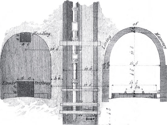
The clear height of the tunnel is 18 feet and its width is 15 feet. The form of the arch is a semi-ellipse sprung from the ends of its conjugate axis, resting upon vertical sidewalls. The course of the railway is straight through the summit ridge and the centre line naturally falls between the two tunnels before described. It was upon this line that the shafts were sunk, so that they were situated on a parallel line, 16 feet off the centre of the tunnel under discussion. The highest point of ground shown on the longitudinal section of the summit ridge (see diagram above) is 1,552 feet over the sea, and 620 feet above the tunnel formation. The two entrances were fixed at an extreme depth of 65 feet of open cutting, which was heavier at the eastern face owing to the ground rising less precipitately.
In consequence of the great depth from the surface to the level of the tunnel, it was calculated that but little time, in proportion to the expense, would be gained by sinking many shafts in addition to opening each entrance face. Accordingly it was determined that there should be but five shafts sunk. The position of each shaft was fixed so as to bring all the various headings of the tunnel to a termination at the same time, or as nearly so as rational pre-judgement could determine. The manner in which they were disposed is as follows (see diagram above).
| From | To | Distance |
| Western face | No. 1 shaft | 1,160 yards |
| No. 1 shaft | No. 2 shaft | 825 yards |
| No. 2 shaft | No. 3 shaft | 648 yards |
| No. 3 shaft | No. 4 shaft | 748 yards |
| No. 4 shaft | No. 5 shaft | 748 yards |
| No. 5 shaft | Eastern face | 1,166 yards |
Total: 5295 lineal yards
The depths of the shafts are as under, expressed from the original surface to the level of the rails.
| Shaft | No. 1 | No. 2 | No. 3 | No. 4 | No. 5 |
| Depth | 182 yards | 189 yards | 162 yards | 189 yards | 135 yards |
Total: 857 lineal yards
From which it appears that the average depth may be taken at 172 yards.
Plan of construction
It was resolved to drive two driftways, one at the top, the other at the formation level of the tunnel, through the entire length, before commencing the general excavation. The size of these headings was – for the top one, 4 feet, and the bottom one, 6 feet square (see diagram below). The object of this mode of proceeding was to meet some points of difficulty that were presented. (The mode of ventilation will be subsequently explained.) It served as a means to carry air to the workings through the long stretches that lay between the various shafts and open ends, as is usual in coal works, by horizontal and parallel galleries; so by placing one of the drifts vertically over the other, the same effect was obtained. The upper one ranged the crown of the tunnel and laid open the work for final excavation, while the bottom one served for the drainage and drawing away the material; both together lessened the quantity of excavation to be afterwards raised and took off the water from the heavier work of the enlargement.
Further, there was pecuniary reason. It was not thought wise to go too headlong into so great and novel a work when, by merely driving driftways, a lesser sum of money was expended in the first instance and when the headings were gotten through the problem was solved, so far as regards the amount of water and knowing the nature of the ground: confidence in the undertaking was established, which enabled the work of greater size to be pushed more vigorously afterwards; and for these reasons it was preferred to drive a double driftway throughout before carrying the full excavation forward or following close after the headings.
The number of shafts, and the manner in which they were disposed, have been already stated. They were 10 feet in diameter and a 25 horse engine was applied at the top of each to wind out the material and work the pumps. It was assumed that the sinking would occupy about 15 months and that in the mean time the headings from the entrance faces would be advanced by as much as the greater lengths of those stretches exceed the distance between any two of the shafts; so that after the horizontal work should commence from the bottom of the shafts, the entire number of faces of operation would have equal spaces to drive before meeting the headings from the opposite direction and thus leave the mountain thrilled at one period of time. It was then proposed to follow up with the widening process and general formation of the tunnel at each face. The plan of ventilation will be detailed; but it may be observed that there was no want of air felt after the communication was opened by the drifts in the way described, between the respective shafts and the open ends of the tunnel. It was only until the headings should be gotten through that any artificial means were requisite.
Preliminary operations
A company was formed in 1836 and the act for the construction of the railway, embracing this important work, was obtained in May 1837. It was 12 months afterwards before any steps were taken for proceeding, owing to the formidable nature of the undertaking. The promoters were not assured and had to contend against the opposing views of timid and dissenting shareholders.
The engineer who laid out and entered upon the construction of this work was Charles Vignoles Esq. He was superseded by Joseph Locke Esq under whose direction it was executed.
The ground was broken on the 1st October 1838 but nothing of a determined nature was done until towards the end of the following year.
The preliminary works that were necessary for commencing the tunnel were not so trifling or such as might be done at once. It was necessary to make cart roads in different directions to convey coal for the engines from the adjacent public roads and also to connect the various points of operation, the united length of which exceeded four miles. It was requisite to build cottages for the workmen, stables, a gunpowder magazine and workshops; besides erecting the engines and constructing the reservoirs, observations etc.
It may not be wrong, at this place, to state a few particulars of the notions that prevailed at the time in question, with respect to a work of this nature.
It was generally said that it would never be made or that, if it were, it must be at an absurdly extravagant cost after many years. The opinions of those most interested were very vague and but few had any idea of how long it would take to construct or how much it would cost. It was thought however by those best able to form a judgement that the strata were generally favourable from the appearance of the bassettings and dip along and in the vicinity of the line; and that passing boldly, as it did, under the centre of the ridge, there should be no ground of a highly broken and contorted character, or (as in sidelong ground) that might occasion a creeping weight and require expensive timbering and lining for its support. The circumjacent valleys lay in such a manner, both in point of position and levels, in respect to the drainage of water from the workings, and the fact of the tunnel being situated 900 feet above the sea led to the belief that the quantity of water from the natural drainage of the surrounding district would not be excessive.
It was also seen that the time of completion must be governed by the mode of construction that might be employed and that, owing to the great depth of the shafts, the number of faces of work most likely would be but few, which shadowed forth in some degree the period for its completion.
Situation and character of the work/geology of the ridge/general design and structure/plan of construction/preliminary operations
Driving the headings/excavation & lining