

Woodhead demonstration
Woodhead demonstration
1/11
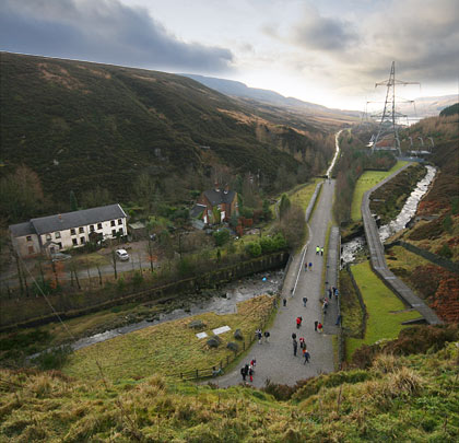
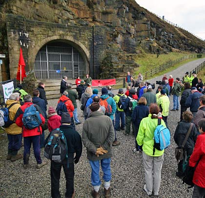
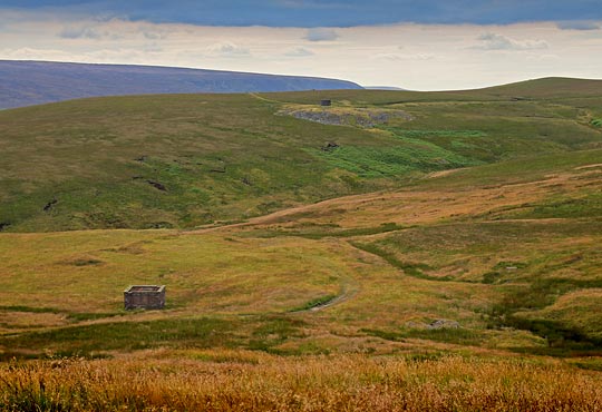
Going home - the foot soldiers head back down the Longdendale Trail.

On this day in 1960, 66 years ago, freight services ended over Tottington Viaduct at the northern reaches of the Holcombe Brook branch.


The first of Woodhead’s two single bores, engineered by Charles Vignoles and Joseph Locke, opened to traffic in 1845. It rises on a 1 in 200 gradient towards Dunford Bridge at its east end. Seven years later, the second tunnel was finished.
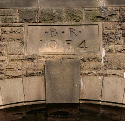
By the end of the Second World War, they were in such poor condition that Halcrow & Partners was contracted to build a new double-track tunnel. The line was also electrified. After five years work, the ribbon was cut by Transport Minister Alan Lennox-Boyd on 3rd June 1954. It cost £4.6million and six lives.
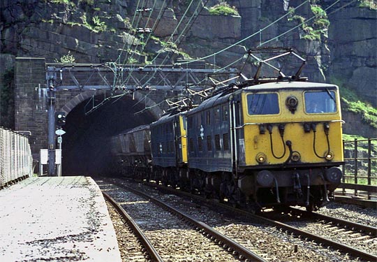
The little-used passenger service bit the dust in January 1970 but it was not until Saturday 18th July 1981 that a Harwich ferry train became the last service ever the pass through the tunnel.
Situation and character of the work/geology of the ridge/general design and structure/plan of construction/preliminary operations
Driving the headings/excavation & lining
The tract of country lying between Manchester and Sheffield is traversed by a well-known ridge of mountains called the Pennine chain, and sometimes the backbone of England, in which the rivers Don and Mersey take their source, and flow in opposite directions to the eastern and western shores.
When the plan of a railway for connecting the towns in question was required, it was early seen that a tunnel through this ridge was unavoidable; and it was also perceived that the best place for getting it through was near the head waters of the rivers that have been named, as their gorges penetrated further up, presented the narrowest limit of the ridge, and their courses downwards through the flanks of the mountain afforded the most desirable route for the railway. This position was found to be nearly midway and not much out of the nearest direction between the two towns. The railway between Manchester and Sheffield merits some notice, not only on account of the work I am describing but for its general design and bold works. The tunnel is situated at the summit level of the railway which falls both to Manchester and Sheffield, with inclinations equal to about forty feet per mile on either side for 18 miles. Such gradients had, at the time, a degree of novel severity; but they afforded the best way by which the great elevation could be reached at which it was practicable to commence the tunnel.
It has been stated that the route of the railway followed the courses of the rivers Don and Mersey. This description is entirely true with regard to the river Don. Its approach to Sheffield enabled the railway on its banks to abut upon the town. It was not so upon the Manchester side. The river Mersey passes wide of that town which involved another tunnel of difficult construction through the ridge at Hattersley, which separates the waters falling into the Mersey from those into the valley of the Tame, as the line approached Manchester. There were also the Dinting and Etherow viaducts, two structures of unusual dimensions, designed by Alfred S Jee Esq, and considerable viaducts over the lateral brooks of the valleys traversed, together with heavy embankments and culverts on sidelong ground, and deep excavations; so that the line may be said to have been one of heavy and difficult works which have been happily overcome.
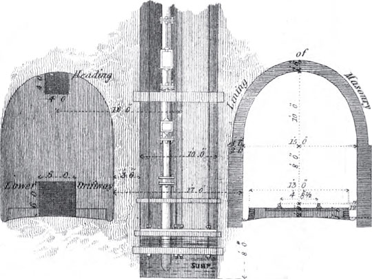
Having described the situation of the tunnel, it is desirable to explain the character of the formations through which it had to be carried, as this is often of more consequence in regard to the construction of such a work than its physical magnitude. The measures passed through were beds of grit, various sandstones and different qualities of shale. The order in which these strata occur is well known – resting upon the limestone, the coal series, passing up through its various beds of grit and sandstone, alternated with argillaceous shales, reaches the lowest seam of workable coal known in Yorkshire, immediately below which lay the whole of the measures that had to be operated upon in driving the tunnel. The disposition of the strata showed a moderate dip to the eastward; but it is not to be inferred that the sheets of rock around and overlying the tunnel were in one continuous plane. They lay in the usual masses of irregular form and area, with various inclinations and insulated by faults (see diagram below). There were no organic remains or mineral ingredients discovered, but those well known in the coal measures; and the only observation worthy of remark with regard to this lower portion of the series (which is not so familiar) is that there was no absence of the usual developments which occur in the upper measures of this class of rocks.
Click here for a detailed PDF diagram showing the section of the summit rock at Woodhead.
It has been stated that the tunnel is situated at the summit of the line. The height of the rails at this point is 966 feet above the sea and marks the eastern entrance. At the western end, the rails are but 887 feet above the same datum, which shows a difference of level, between one end and the other, of 79 feet. The distance between these limits is 3 miles and 22 yards, the total length of the tunnel.
The stratification has been described as dipping eastward. The gradient of the tunnel rises in the same direction, with a uniform inclination from end to end of 1 in 200.
From the first, it was laid out to have two parallel tunnels of smaller dimensions, instead of one larger and calculated for a double trackway. This was determined in order to save immediate outlay, with a view of constructing but one of the tunnels in the first instance and leaving the second one in abeyance until increased traffic should require its construction. This practice deserves commendation, with respect to tunnels of such magnitude as that I am describing, not only from the lesser difficulty of raising the smaller capital but in consequence of the lesser quantity of excavation requisite to be drawn from the limited number of faces of operation used; and it does not appear to me that the ultimate cost of the two tunnels should generally exceed that of the larger size, if the ground be at all of a friable nature. The thickness of the space between the two tunnels, was designed at 17 feet and that lying the more southerly was the one executed and to which the observations in this paper refer.
The clear height of the tunnel is 18 feet and its width is 15 feet. The form of the arch is a semi-ellipse sprung from the ends of its conjugate axis, resting upon vertical sidewalls. The course of the railway is straight through the summit ridge and the centre line naturally falls between the two tunnels before described. It was upon this line that the shafts were sunk, so that they were situated on a parallel line, 16 feet off the centre of the tunnel under discussion. The highest point of ground shown on the longitudinal section of the summit ridge (see diagram above) is 1,552 feet over the sea, and 620 feet above the tunnel formation. The two entrances were fixed at an extreme depth of 65 feet of open cutting, which was heavier at the eastern face owing to the ground rising less precipitately.
In consequence of the great depth from the surface to the level of the tunnel, it was calculated that but little time, in proportion to the expense, would be gained by sinking many shafts in addition to opening each entrance face. Accordingly it was determined that there should be but five shafts sunk. The position of each shaft was fixed so as to bring all the various headings of the tunnel to a termination at the same time, or as nearly so as rational pre-judgement could determine. The manner in which they were disposed is as follows (see diagram above).
| From | To | Distance |
| Western face | No. 1 shaft | 1,160 yards |
| No. 1 shaft | No. 2 shaft | 825 yards |
| No. 2 shaft | No. 3 shaft | 648 yards |
| No. 3 shaft | No. 4 shaft | 748 yards |
| No. 4 shaft | No. 5 shaft | 748 yards |
| No. 5 shaft | Eastern face | 1,166 yards |
Total: 5295 lineal yards
The depths of the shafts are as under, expressed from the original surface to the level of the rails.
| Shaft | No. 1 | No. 2 | No. 3 | No. 4 | No. 5 |
| Depth | 182 yards | 189 yards | 162 yards | 189 yards | 135 yards |
Total: 857 lineal yards
From which it appears that the average depth may be taken at 172 yards.
It was resolved to drive two driftways, one at the top, the other at the formation level of the tunnel, through the entire length, before commencing the general excavation. The size of these headings was – for the top one, 4 feet, and the bottom one, 6 feet square (see diagram below). The object of this mode of proceeding was to meet some points of difficulty that were presented. (The mode of ventilation will be subsequently explained.) It served as a means to carry air to the workings through the long stretches that lay between the various shafts and open ends, as is usual in coal works, by horizontal and parallel galleries; so by placing one of the drifts vertically over the other, the same effect was obtained. The upper one ranged the crown of the tunnel and laid open the work for final excavation, while the bottom one served for the drainage and drawing away the material; both together lessened the quantity of excavation to be afterwards raised and took off the water from the heavier work of the enlargement.
Further, there was pecuniary reason. It was not thought wise to go too headlong into so great and novel a work when, by merely driving driftways, a lesser sum of money was expended in the first instance and when the headings were gotten through the problem was solved, so far as regards the amount of water and knowing the nature of the ground: confidence in the undertaking was established, which enabled the work of greater size to be pushed more vigorously afterwards; and for these reasons it was preferred to drive a double driftway throughout before carrying the full excavation forward or following close after the headings.
The number of shafts, and the manner in which they were disposed, have been already stated. They were 10 feet in diameter and a 25 horse engine was applied at the top of each to wind out the material and work the pumps. It was assumed that the sinking would occupy about 15 months and that in the mean time the headings from the entrance faces would be advanced by as much as the greater lengths of those stretches exceed the distance between any two of the shafts; so that after the horizontal work should commence from the bottom of the shafts, the entire number of faces of operation would have equal spaces to drive before meeting the headings from the opposite direction and thus leave the mountain thrilled at one period of time. It was then proposed to follow up with the widening process and general formation of the tunnel at each face. The plan of ventilation will be detailed; but it may be observed that there was no want of air felt after the communication was opened by the drifts in the way described, between the respective shafts and the open ends of the tunnel. It was only until the headings should be gotten through that any artificial means were requisite.
A company was formed in 1836 and the act for the construction of the railway, embracing this important work, was obtained in May 1837. It was 12 months afterwards before any steps were taken for proceeding, owing to the formidable nature of the undertaking. The promoters were not assured and had to contend against the opposing views of timid and dissenting shareholders.
The engineer who laid out and entered upon the construction of this work was Charles Vignoles Esq. He was superseded by Joseph Locke Esq under whose direction it was executed.
The ground was broken on the 1st October 1838 but nothing of a determined nature was done until towards the end of the following year.
The preliminary works that were necessary for commencing the tunnel were not so trifling or such as might be done at once. It was necessary to make cart roads in different directions to convey coal for the engines from the adjacent public roads and also to connect the various points of operation, the united length of which exceeded four miles. It was requisite to build cottages for the workmen, stables, a gunpowder magazine and workshops; besides erecting the engines and constructing the reservoirs, observations etc.
It may not be wrong, at this place, to state a few particulars of the notions that prevailed at the time in question, with respect to a work of this nature.
It was generally said that it would never be made or that, if it were, it must be at an absurdly extravagant cost after many years. The opinions of those most interested were very vague and but few had any idea of how long it would take to construct or how much it would cost. It was thought however by those best able to form a judgement that the strata were generally favourable from the appearance of the bassettings and dip along and in the vicinity of the line; and that passing boldly, as it did, under the centre of the ridge, there should be no ground of a highly broken and contorted character, or (as in sidelong ground) that might occasion a creeping weight and require expensive timbering and lining for its support. The circumjacent valleys lay in such a manner, both in point of position and levels, in respect to the drainage of water from the workings, and the fact of the tunnel being situated 900 feet above the sea led to the belief that the quantity of water from the natural drainage of the surrounding district would not be excessive.
It was also seen that the time of completion must be governed by the mode of construction that might be employed and that, owing to the great depth of the shafts, the number of faces of work most likely would be but few, which shadowed forth in some degree the period for its completion.
Situation and character of the work/geology of the ridge/general design and structure/plan of construction/preliminary operations
Driving the headings/excavation & lining

 July 2008
The Pennines were squeezed from the earth to form Britain’s backbone about 400 million years ago, give or take; the railways have been around for the blink of an eye. The former presented an inconvenient barrier when the latter was pushing its buffer stops to new destinations through the 19th century. But it was a challenge that gave rise to the great trans-Pennine tunnels – Standedge, Doves Hole, Totley, Cowburn – linking the north’s valleys to usher in the age of the train. Whilst the first step on that adventure was taken by Summit Tunnel in the hills above Littleborough, following closely behind was an enterprise that pushed every boundary before eventually falling victim to the blind march of ‘progress’.
Railway promoters kept parliament busy in 1836, depositing more than a hundred bills for its consideration and approval. Amongst these was the Sheffield Ashton-under-Lyne & Manchester Railway (SA&M), led by Lord Wharncliffe, backed by 56 local bigwigs and guided by engineer Charles Vignoles. Over the course of that summer, Vignoles and Joseph Locke independently surveyed routes, coming together in October to reconcile any differences. Their joint plan involved a summit 966 feet above sea level at the eastern end of a tunnel stretching for over three miles. As an economy measure, this would be built to accommodate just a single track but with provision made for a second bore alongside it should the need arise. And so, on 1st October 1838, Wharncliffe’s spade broke the ground at the western end of what, seven years later, would become Woodhead Tunnel.
This was a desolate place, in the back of beyond. Gearing up took many months. Accommodation had to be built for the workforce, stables for the horses, a magazine for the gunpowder; cart tracks were laid across the moor and machinery assembled upon it. It was the autumn of 1839 before real inroads were made.
Progress benefitted from five construction shafts – 10 feet in diameter and taking upwards of two years to sink. The deepest plunged 567 feet into the millstone grit; the shallowest 405 feet. To haul out material and drive the pumps, a 25 horsepower steam engine was harnessed at each. The tunnel itself was offset from their base by 16 feet at its centreline so that the shafts would sit between it and the second bore, should one subsequently be added. From 12 working faces, the two headings were driven – one later forming the crown of the tunnel, with the other positioned below it. When all eventually met, the greatest inaccuracy in line and level was just three inches.
With this initial work fulfilled by 400 navvies under the SA&M’s employ, contractors were then appointed to complete the excavation and insert the lining – the greater eastern section being awarded to Thomas Nicholson, with Richard Hattersley allocated the remainder. When activities reached their peak, 1,500 men were said to be employed there; 32 of them didn’t survive the experience, 250 suffered serious injuries.
On Saturday 20th December 1845, the company’s directors and engineer accompanied General Sir Charles William Pasley, the Board of Trade’s Inspector of Railways, through the tunnel – their train propelling a wagon of torch-bearing men so that this £201,210 black hole could be closely examined. It was, Pasley declared, “one of the finest pieces of engineering I have ever seen”.
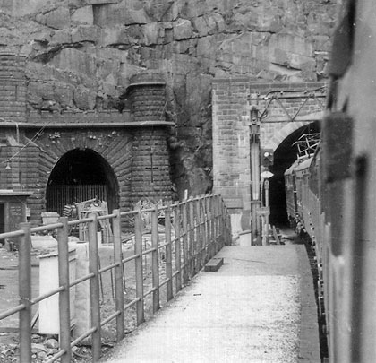
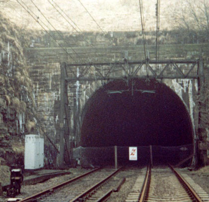
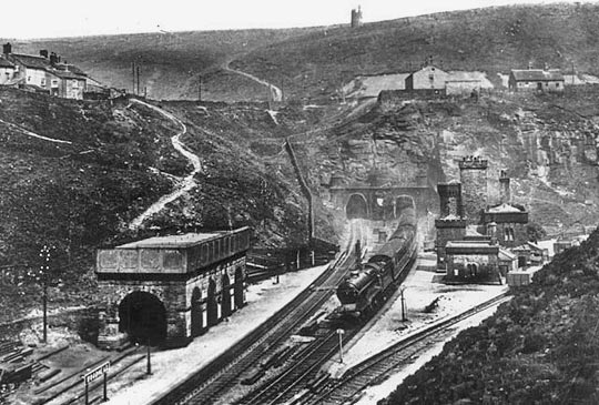
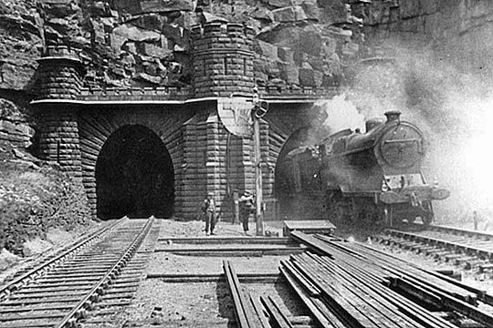
Woodhead was visited by its inaugural revenue-earning service the following Monday. Two engines pulled 20 coaches through it in ten minutes, enjoying the falling 1:201 gradient from the eastern end at Dunford Bridge. They had passed beneath a soffit 18 feet above rail level; springing was at 10 feet. The lining varied in thickness from 18-36 inches – even more in areas of particularly weak ground – but was deemed altogether unnecessary for 300 yards where the millstone grit remained exposed. Two-foot deep drainage channels on both sides of the 15-foot wide bore carried away penetrating water whilst, into the north wall, 25 arches were cut at intervals of around 200 yards to ease the construction of a second tunnel. Cutting edge technology, in the form of Cooke & Wheatstone’s patent magnetic telegraph, allowed the guards at either end to communicate with one another.
Every train to travel Woodhead’s single line was drawn by a lone pilot engine. This approach ensured that only one train could ever be in the tunnel at any time, so rendering a collision impossible. But it soon became a serious constraint on the route. With the line under new ownership – that of the Manchester Sheffield & Lincolnshire Railway – work to extend the arches to form cross headings got underway in the spring of 1847 and, from these, another tunnel was bored for Sheffield-bound (Up) traffic. It was a protracted if relatively mundane venture, with spoil removed via the passages to waiting wagons. But cholera stalked the navvies’ western encampment in 1849, claiming 28 victims in a matter of weeks.
As 1852 arrived, the tunnel was receiving its finishing touches and deemed ready for inspection. But a 15-yard bulge had appeared in one of the side walls when Captain George Wynne of the Royal Engineers arrived to give it the once over on the 16th January; the masonry had to be taken down and rebuilt. He returned on 21st to find it “in a fit state for the conveyance of passengers” and the new Up tunnel was brought into service on 2nd February. In terms of dimensions, it was almost identical to its neighbour but lined throughout.
Maintaining the tracks was a gang comprising two foremen and five labourers. There was a fair turnover amongst this number – some left believing the tunnels caused sickness, although a few were engaged therein for several years. All agreed it was a bad place to work, particularly the newer bore through which trains laboured up to Dunford Bridge. In 1863, an American visitor described the experience of being in the tunnels. “As the train approaches you feel the air driven forward, and also rushing through the openings into the other tunnel. The moment the train has passed it pours back again to follow the train. At the shafts the current was uniformly down and very strong, both at the time trains were in the tunnel and when they were not. A great deal of water was dripping from them all, amounting in some to a small stream. This fortunately did not fall upon the track, but in the arched chamber or opening between the tunnels where boards and masonry were arranged to receive it and carry it to the drains.”
By 1899 the Great Central had taken over and, to increase capacity, the company installed intermediate signals on the Up line, controlled from a box established in No.12 cross passage. Those prepared to man it – and there weren’t many – worked shorter six-hour shifts. But smoke contrived to mask the signals and many trains held by them found it difficult to get going again owing to the rising gradient. Conditions brought about the box’s abandonment in 1909. Hoping to improve matters, work to increase the diameter of No.2 shaft got underway in the autumn of 1912 – a £12,000 project that would take three years to complete.
Conditions aside, there was no denying Woodhead’s success. An average of 80 trains daily – the majority of them carrying coal westwards or empties back to Yorkshire – made the journey through the hill. But their impact on the tunnels’ lining was severe, eroding the mortar holding it together. The route’s electrification had been given the green light in 1936 and, once hostilities with Germany had come to an end, a substantial programme of renovations was initiated, conducted within overnight and weekend possessions. The decline though proved too great. In 1946, the civil engineering department was granted nine-month occupations of each bore in turn – single line working was instituted through the other tunnel whilst some traffic was diverted via alternative routes. Even then, when these periods were over, it was realised that a more radical solution would have to be implemented to avoid a repeat of the exercise.
And so the foundations were laid for a new tunnel. Authorised by the Railway Executive on 15th November 1948, it would be built for two tracks to the south side of the original Down tunnel, separated from it by 77 feet except for the westernmost 200 yards where a curve of 40 chains radius reduced that distance to 27 feet. Unlike its elder siblings, the summit would be reached one mile in from the Dunford Bridge end, with falling gradients of 1:129 and 1:1,186 to the west and east sides respectively.
Sir William Halcrow & Partners were appointed as designers and consulting engineers, the construction contract being let to Balfour Beatty. Directing the venture was Eastern Region’s Chief Engineer John Campbell whilst the resident engineer was J D Dempster.
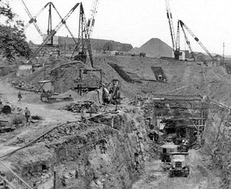
In February 1949, the hills became alive again to the sounds of industry. Dunford Bridge Camp grew for the workforce of 1,100, complete with cinema, clubs and a Post Office. There was a proper sanitation system too. But this was not the manual enterprise witnessed a hundred years earlier; this time a new generation of plant and equipment would cut timescales and costs. Or so everyone thought.
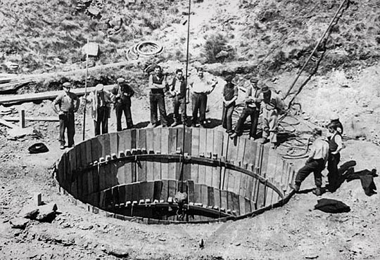
The engineer’s plan for three construction shafts was changed in favour of the contractor’s proposal for just one – 16 feet in diameter and located 2,610 yards from the Woodhead end, about 60 yards west of the midpoint. On the surface, this coincided with a shallow valley, reducing its depth to 467 feet. It was sunk 26 feet south of the centreline, thus separating lifting operations from those taking place in the tunnel itself. From its base, 12-foot square headings were thrust in both directions to meet those advancing from the portals. The rock was displaced with gelignite; side-tipping skips hauled by battery-powered locomotives carrying the spoil away for disposal.
The plan was to enlarge the heading to full section by means of radial drilling. This though had to be abandoned as the shaly nature of the millstone grit – through which three-quarters of it was driven – brought uncontrollable results, with considerable overbreaks. A hasty reorganisation of the work was required, allowing it to progress from more than the four faces. But this in itself created logistical difficulties and the rate of progress slowed to a fraction of that demanded by the programme. Then, in 1951, two sections collapsed, one of them – 300 yards from the Woodhead end – left a void reaching 70 feet into the roof. Work there was delayed for six months.
The consequence though was the provision of haulage ways parallel to the heading and connected to it at intervals, these extending for around two miles. They effectively brought salvation – allowing nine additional working chambers to be opened up and, with them, the default installation of steel reinforcement ribs as the full excavation progressed. Whilst this proved costly and caused much consternation amongst the bean counters, it prevented the Pennines from falling on anyone’s head.
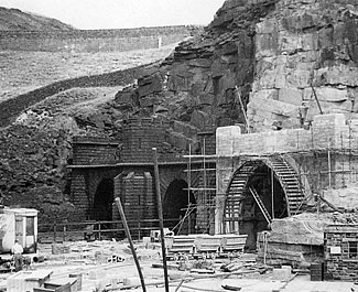
At 3 miles 66 yards, the new tunnel was 131 feet longer than its neighbouring single bores. Lined with mass concrete not less than 21 inches thick, its horseshoe shape provided a span of 27 feet and height from rail to soffit of 20 feet 7¼ inches. No invert was needed. To help ventilate the summit section, an 8-foot diameter stope was bored, 1,205 yards from the Dunford Bridge end, to connect with the easternmost (No.5) shaft of the Victorian tunnels. To improve the lot of future maintenance teams, a mess room was provided at its midpoint and permanent lighting installed.
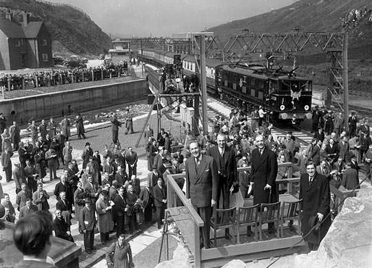
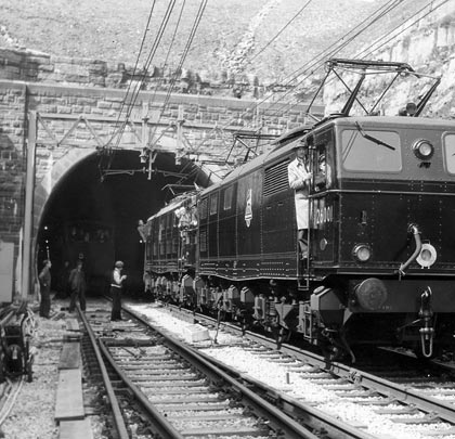
Completed in October 1953, Woodhead New cost £4.25 million – £1.8 million over budget – and six lives. The first trains to pass through under 1,500V DC electric traction did so on 30th May 1954, with regular workings getting underway a fortnight later. Alan Lennox-Boyd, Minister of Transport, officially cut the ribbon on 3rd June.
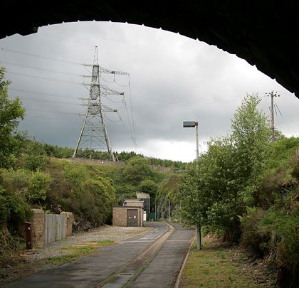
In January 1964, consent was granted for a new 400kV electricity transmission line between Thorpe Marsh near Doncaster and Stalybridge. Supported by others, the Peak Park Planning Board successfully argued that the infrastructure should be below ground between Dunford Bridge and Woodhead. To that end, the Central Electricity Generating Board acquired the two Victorian tunnels. But preparing them for a new life would involve considerable works so, in order to meet immediate demand, the Board was permitted to install temporary cables over the hill.
In the Up bore, thick soot was blasted away with air jets and mixed with ballast, cement and lime to create a hard floor. Voids behind the bulging lining were grouted and huge areas repointed, amounting to about half the tunnel. Three of the shafts were backfilled and sealed whilst No.5 had rubble dropped to a height of 40 feet, below the level of the stope. But shaft No.2 – having already been widened to 16 feet in diameter – was also repointed and retained in case of future ventilation needs.
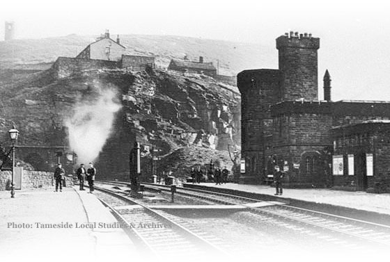
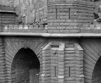
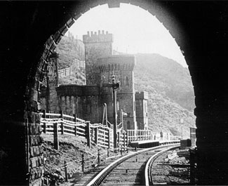
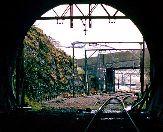
Slightly younger and continuously lined, the Up tunnel was chosen as host for the cabling which was insulated within oil-filled pressurised tubes and immersed in a water trough. Alongside it, a narrow gauge railway was laid for access purposes. Next door in the Down tunnel, oil tanks were fitted. The portals, delightfully castellated when built, were reshaped to make way for ducting. Following an investment of £2.75 million, the switch was thrown and Woodhead’s two electrical circuits went live in 1969.
Whilst envisaging a bright future for the Woodhead line as a conduit for freight, Richard Beeching’s 1963 ‘reshaping’ report effectively triggered its downfall. Amongst the list of proposals was the withdrawal of Sheffield-Manchester passenger services from the Hope Valley route. When the Minister of Transport refused to approve this, attention turned to services via Woodhead which served fewer communities. British Rail’s intention to sever them prompted an outcry and an enquiry, but its decision was eventually upheld and the last scheduled passenger train made its way through the tunnel on 4th January 1970. Then goods traffic, also dwindling, came under scrutiny too. Just 27 years after the new tunnel opened, a Harwich ferry train emerged from it as dawn broke on Saturday 18th July 1981, despatching into history the most audacious part of Lord Wharncliffe’s railway.
Campaigners still worked for a reprieve and, for several years, a rusting single track ventured through the open entrances to the tunnel. But it was lifted in 1986, extinguishing all remaining hopes. Two years later, a collapse near the midpoint of the original Down tunnel and concerns about ongoing maintenance costs prompted the CEGB to add the 1954 bore to their estate; this was acquired in 1993, reputedly for £1 – the intention being to fit new cables in it when the existing ones became life expired. In the meantime, ‘running repairs’ were carried out to the single bores with cavities grouted, more pointing, buttresses and steel ribs installed, and some sections lined in concrete. The costs were considerable, amounting to £15 million. Then in 1990, a stop-joint fire in the Up tunnel caused extensive damage, six years after which an oil fire occurred in the Down. The incentives to move next door were mounting up.
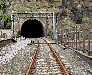
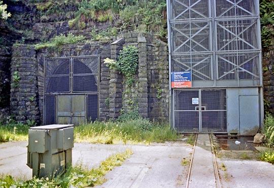
With the remaining trans-Pennine lines becoming victims of their own success, the railway’s strategic planners were tasked with finding more capacity to satisfy medium-term demands – both passenger and freight. Whilst they focussed on existing routes, campaigners and business leaders pointed at Woodhead. With a potential conflict brewing over use of its tunnel, the National Grid sought advice from the Department for Transport about the likelihood of the railway returning. There are no plans, it was told. The ensuing political wrangle fizzled out and preparations for the installation of new cables got underway in early 2008. Once live, the Victorian bores were decommissioned and had their ends unceremoniously filled with concrete, condemning these historic structures to abandonment.
Predicting the future is a talent few are able to perform with any degree of certainty, particularly in an era of economic turmoil and rapid technological development. The case for Woodhead’s revival could grow ever stronger or sink without trace. From a freight perspective, the 16-mile gap between Penistone and Hadfield is perhaps a side-show given that the logical connecting routes – via Tiviot Dale and the formidable Worsborough incline – have also been lost. If accepted, Network Rail’s Northern Hub strategy will deliver much needed capacity for passenger services and possibly restore the tracks through two other disused Victorian bores, those at Standedge.
Whatever the prospects for the three tunnels at Woodhead, there can be no rewriting of their past. The first one was engineered against the odds; the second overcame disease. A century later, the third was caught between a rock and a hard place. All three represent tenacious victories over the forces of nature, rightfully securing prominent entries in the railway’s history book.
| Woodhead tunnels | Historical overview from Wikipedia |
| Work in Progress | BTF film featuring the 1954 tunnel’s construction |
| Reopen the Woodhead Line | Webpage of the campaign group |
| National Grid | Details of the cable replacement project |
Forgotten Relics records and celebrates the UK's disused railway structures, still standing as monuments to the period of ambition, courage and endeavour during which they were built.
Last updated 29 December 2025
Content © 2025 Four by Three | Wordpress Theme © 2024 James Perry