On this day in 1960, 66 years ago, freight services ended over Tottington Viaduct at the northern reaches of the Holcombe Brook branch.
Featured videos...
Join us socially...
Wilmington's second swing bridge
Source: Engineering
Published: 31st January 1908
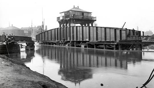
Wilmington’s second swing bridge
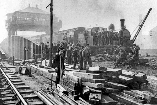
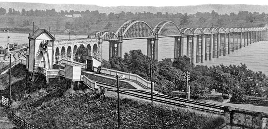
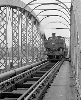
A view of the first train to pass over the new Wilmington bridge on Sunday 5th May 1907.Photo: Mick Nicholson collection
This bridge has been constructed to replace a wrought iron swing bridge, erected by Thomas Cabry in 1853, to carry the Victoria, or East Dock, Railway over the River Hull upon which river is founded the ancient town (now city) of Kingston-upon-Hull. The dock which gave the name to this railway, and which is now known as the Victoria Dock, lies to the east of the river, and north of the ancient citadel, whilst the railway, originally skirting the northern suburbs of the town from east to west, at the present time passes through the thickly populated districts of Sculcoates, Southcoates and Drypool, and forms connection with the subsequently formed railways leading to the seaside resorts of Hornsea and Withernsea.
The railway traffic was very busy and the North Eastern Railway company experienced great difficulty in passing it over the old single-line bridge, particularly as the speed and axle loads were both restricted, although the bridge had been strengthened more than once to meet the more modern requirements. The new bridge is designed for a double-line railway. The Hull Corporation agreed with the railway company to provide, at the Corporation’s cost, a public footway, and this is carried on brackets on the north side of the bridge.
The new bridge was built in close proximity to the old one, notwithstanding that it involved interference with the working of the old bridge, thus necessitating the construction of a temporary foundation on the east bank of the river at a point just clear of the old bridge when opened for river traffic, and of the east abutment of the new bridge. A site, either north or south, which would not interfere with the swinging of the old bridge, would have involved sharp curves in the railway and very great cost by interference with important buildings.
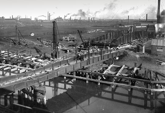
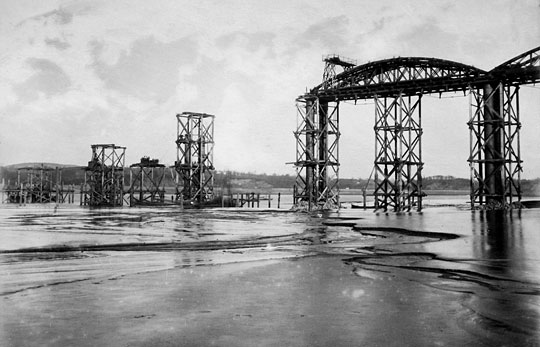
Captured on 25th October 1906, the original bridge is seen still in position, with the new one under construction in the background. Photo: Mick Nicholson collection
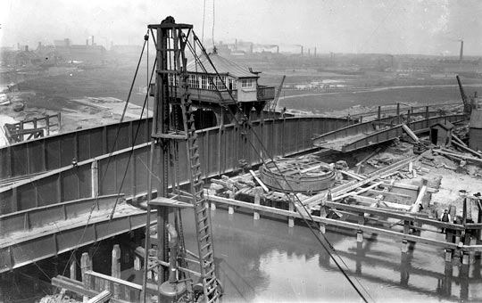
The clear waterway of the old bridge was 37ft 6in, whereas in the new bridge it is 53ft 6in, and provision has also been made under the east, or land, arm for an additional waterway of 40ft in connection with the future widening of the river. The increase in the waterway necessitated a considerable amount of dredging of the river bed, the setting back of the west abutment, and the provision of a substantial river wall about 100 yards long. A clearer idea of what we wish to convey will be gained by reference to the photograph above, which shows the old bridge in the foreground. The far bank of the river is the east bank.
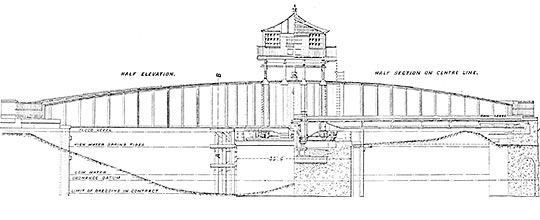
The particular design adopted for the new bridge was largely determined by local conditions. The rail level over the new bridge was fixed by the public road level crossing at the west end of the bridge. It was not possible to raise this level more than 12in, and maintain the road traffic over the crossing. The depth for construction of the steelwork was limited by the height of the water level in the river during floods, the highest recorded flood level being 15.38ft above Ordnance datum, and 4.20ft below the new rail level. By adopting the method of carrying the bridge on a centre pivot a considerable saving in depth was obtained over the usual method of construction of rollers, with an upper and lower roller path.
The bridge is built on a skew of 75deg 33min, is 160ft over all, and is 29ft 6in wide centre to centre of main girders. The main girders have plate-webs, and are hog-backed, being 14ft deep at the centre, and 7ft at the ends. The bridge floor consists of rail bearers with cross girders. At the centre of the bridge there are two special cross girders designed to transmit the whole weight of the bridge, by means of a forged steel crosshead and two steel suspension bolts, to the centre pivot upon which the bridge turns. The steel crosshead and the cast iron centre pivot were tested after manufacture with a proof load of 1,000 tons, and the two suspension bolts and the two special cross girders received a proof load of 500 tons each. These proof loads were intended to be 50 per cent in excess of the greatest load to be carried.
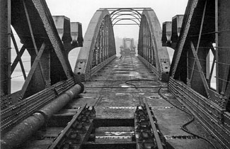
The bridge was completed on the temporary foundation, above referred to, on the east bank of the river, and after completion it was intended to balance it there previous to moving it to the permanent position; but owing to a settlement which took place under the temporary centre pier, this could not be done. Its position during erection may be seen in the photograph above, behind the old bridge.
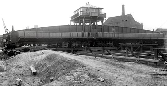
The bridge (including machinery), when completed, was moved into position along a specially constructed path, consisting of a double row of piles with waybeams, and a double line of rails under each main girder. The bridge was carried by eight six-wheeled bogies placed as close to the centre of the bridge as possible, four under each main girder. They were designed to carry a load of 90 tons each. In order that the centre pivot, when travelling with the bridge, should clear the east abutment and top of the roller-path on the centre pier, it was necessary to erect and launch the bridge at a level 3ft 10in higher than it would occupy upon the permanent site.
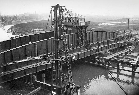
The bridge being hauled into position. Photo: Mick Nicholson collection
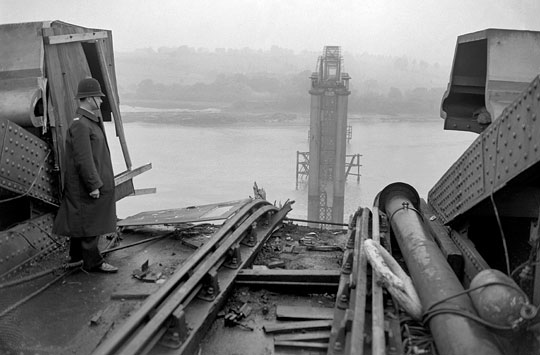
The bridge was hauled into position by a wire cable attached to a locomotive, the power being increased about 12 to 1 by means of blocks etc. The bridge moved freely when travelling. Some delay, however, was caused by two of the rails upon which the bridge was travelling breaking just at the edge of the abutment. These breakages also caused one of the tyres to be sheared off one of the bogies under each main girder. The bridge, when brought into position on the centre pier, was lowered by means of four hydraulic jacks, placed two on each side of the centre pier, under the ends of cross girders 9 and 12, the position of the bridge being finally adjusted by sliding it on greased rails, plates, and rollers by means of jacks placed on the centre pier. The bridge may be seen in position while being hauled in the photograph above; below is the old bridge removed from its foundation.
The old bridge removed from its foundation. Photo: Mick Nicholson collection
The total weight of steel and ironwork in the bridge is about 460 tons, and the launching weight about 500 tons. The bridge was finally balanced after it was lowered on to its permanent site.
A general description of this bridge having been given, a more detailed account of the turning gear and the way in which the bridge is manipulated will be interesting.
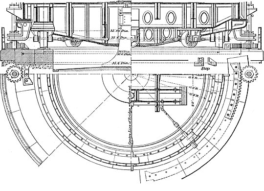
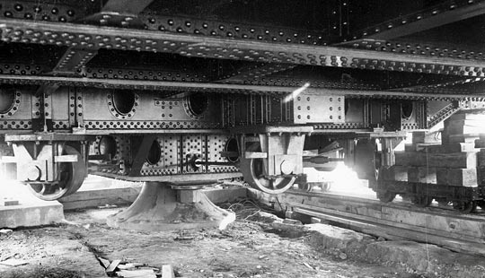
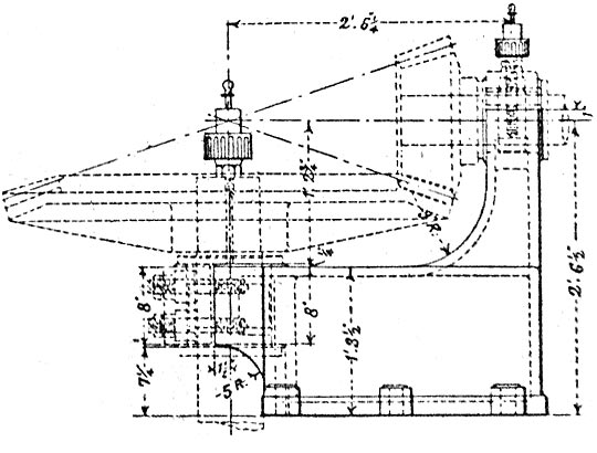
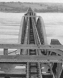
A steel roller path, with eight steadying rollers, is provided. The arrangement of the rollers and centre pivot is shown in the diagram above. If it should be necessary at any time to take the weight of the bridge off the centre pivot in order to renew the bearing discs etc, sufficient rollers have been provided to enable the bridge to be turned as usual, the four centre cross girders being specially designed to take the abnormal loads induced thereby. The centre pivot and rollers are also shown in the photograph below.
Arrangement of the centre pivot and rollers. Photo: Mick Nicholson collection
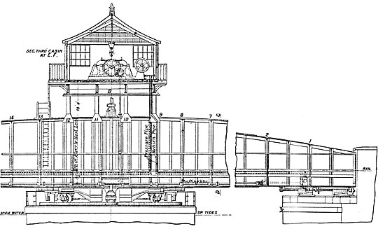
At each end of the bridge, under the bottom flanges of the main girders, wedges sliding into rest plates at the corners of the two abutments are provided to take out the droop of the bridge after swinging, and to fix the bridge in position for railway traffic. These are shown below.
The centre pier, which carries the centre pivot and the roller path, is constructed entirely of 6 to 1 concrete, as are also the two abutments, and the foundations are carried down to the clay which overlies the chalk. This clay is approximately 22ft thick. These foundations are about 19ft below Ordnance datum and approximately 21ft below low-water level. Owing to the proximity of the new bridge to the old one, and also to the nature of the material passed through – this material being silt and warp – great anxiety was caused during the sinking of these foundations, and special precautions were taken by means of trestles, strutting, and tying back the centre pier and abutments of the existing bridge, to prevent settlement or movement as far as possible. It was only possible to use a single-walled cofferdam for the centre pier, and this, composed of 12in by 12in piles tongued and grooved, stood very well.
As the level of the roller path is 12.55ft, and the highest recorded flood level 15.38ft Ordnance datum, it has been necessary to surround the top of the centre pier with a cast iron shield 3ft 6in high, thoroughly caulked and made watertight to keep the spring tides from overflowing into the centre pier.
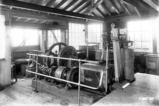
An interior view of the overhead cabin. Photo: Mick Nicholson collection
The machinery for inserting and withdrawing the wedges and for turning the bridge is carried in an overhead cabin. An interior view is provided above. The machinery for operating the bridge and withdrawing the wedges by power is in duplicate, and has interchangeable hand-gear for turning the bridge and withdrawing the wedges. The motive power is electricity, supplied by the Hull Corporation. It is conveyed across the river by means of an overhead armoured cable, supported by two steel lattice masts 150ft high, the end of the cable being dropped through the roof of the overhead cabin. The motors, which may be seen in the figures previously referred to, are series wound, and were made by Messrs Siemens Brothers and Co Limited. They are each capable of developing 30 horse-power at 440 volts, and revolve at 240 revolutions per minute.
Each motor is fitted with a double-pole switch and automatic cut-out and fuses, and is controlled by a Siemens’ controller with gridiron resistances. For swinging the bridge, these motors can be worked together, but each motor must be worked by its own controller. The commutator is made of hard-drawn copper, and should stand an inch of wear before it requires to be renewed. The brushes are of carbon, and sparking is guaranteed not to take place until 50 per cent above the estimated load is reached (45 horse-power). The switch-board, which is also fitted for lighting purposes, has the necessary ampere-meter and volt-meter, and was made by Messrs Siemens Brothers. The bracket carrying the bevel-wheel and pinion, which transmit the power down to the circular rack on the top of the foundations, are shown with the wheel and pinion below.
The horse-power required to work the bridge is approximately as follows –
Starting
Finishing
Withdrawing wedges
17.7hp
13.25hp
Swinging bridge
26.5hp
17.7hp
Inserting wedges
13hp
14.75hp
The bridge was opened and closed 30 times at an expenditure of 12½ electrical units. The average time per cycle was two minutes.
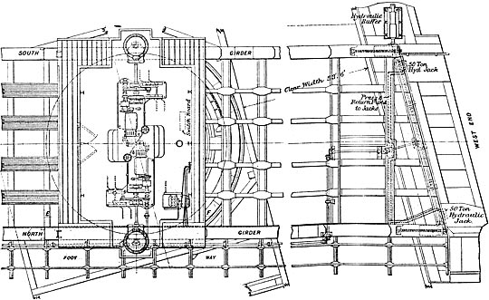
In order to facilitate the withdrawal of the wedges by hand when required, by taking the weight of the bridge off the wedges, two hydraulic rams are provided at each end of the bridge. They may be seen in the diagram below. The pump for actuating the rams is in the overhead cabin, and may be seen on the right-hand side of the turning gear. The overhead cabin also contains the necessary levers for working and locking up the bridge. The bridge is in charge of an experienced mechanic, assisted by two steersmen, who divide the duties into three shifts. Three signal boxes control the working of the bridge, two being outpost boxes 345 yards and 455 yards respectively from the centre of the bridge, and the other, the Sculcoates station box, near the west end of the bridge, being for the central control and also for the station and level crossing.
When the bridge is to be opened for river traffic, the bridgeman by bell cable notifies the signalman in Sculcoates station box, who, if no train has been accepted, places his levers, when not already so placed, to the normal position, pulls over a lever to release the bridge, and by a plunging instrument indicates to the bridgeman that the bridge is free for working. The bridgeman will then back-lock the releasing lever in Sculcoates station box, operate the levers which work the latch-bolt of the bridge to disengage the signal rodding, and finally withdraw the wedges and turn the bridge. Special lock and block instruments with plungers are provided at Sculcoates station box, and instruments without plungers at the outpost boxes. The dials of the instruments give the usual indications of the state of the section or trains in both directions, and bells are also provided for indicating the class of train in the usual way. Directly the signalman at either of the outpost boxes replaces the signal for the line leading to the bridge to “Danger”, the signal levers become automatically locked, and cannot again be pulled over until the Sculcoates station signalman plunges his instrument to release the lever electrically. The signals for the lines approaching the bridge at all the three boxes are so electrically controlled by the wedges of the bridge that the signal arms will not fall to the “All right” or “off” position until the wedges are fully home; and if the wedges are partially withdrawn during the time any signal is “off”, the movement will cause the arms to be placed to the “on” or “Danger” position. Telephones connect the three signal boxes, and also connect the overhead cabin with Sculcoates station box.
The north side of the finished structure, showing the public footway. Photo: Mick Nicholson collection
The bridge was designed by Mr J Triffitt, A M Inst C E, assistant engineer, under the superintendence of Mr W J Cudworth, M Inst C E, chief engineer of the southern division of the North Eastern Railway. Mr W McD’Malt was the resident engineer on the work, and Mr H Bruff assisted in the preparation of drawings and in the superintendence of the work. The chief contractors for the work were Mssrs Harman and Langton, of Hull, and the subcontractors for the steelwork Messrs John Butler and Co Limited, Staningley, Leeds, who entrusted the erection to Mr R Woods, of Westminster.
The machinery for turning the bridge and withdrawing the wedges was designed by Mr Wilson Worsdell, M Inst C E, chief mechanical engineer for the North Eastern Railway company, whose contractors were Messrs Cowans and Sheldon, of Carlisle. The signalling and overhead masts were supplied by Messrs Mackenzie and Holland, Worcester.
A view of the completed bridge, open to allow the river traffic to pass. Photo: Mick Nicholson collection
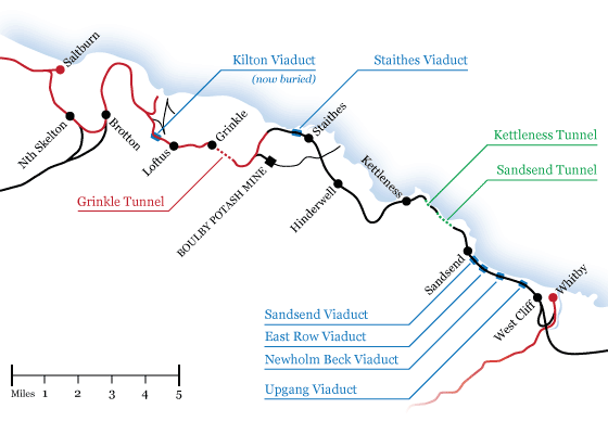
The Whitby to Loftus line, opened on 3rd December 1883, was a little more than 16 miles in length, from Bog Hall Junction (26 chains from Whitby station) to an end-on connection with the North Eastern Railway at Loftus.
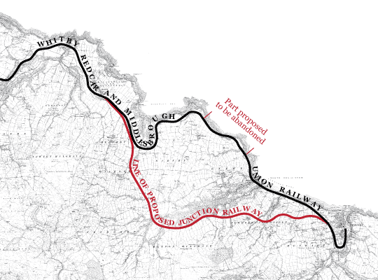
The first proposal, in 1863, for a line along the coast northwards from Whitby was that of the Scarborough, Whitby & Staithes Railway which, in 1864, was rejected by committee in the House of Commons. According to the map, the line between Whitby and Sandsend would have been built a little further inland than was ultimately the case. Between Sandsend and Kettleness the course was more or less similar to that which was eventually built, although the map and the plans give no indication of any tunnelling or, indeed, any cliff-edge work. From Kettleness to Hinderwell the line would have taken a route close to the sea and Runswick village than was eventually constructed. The route on the plan appears to have been rather carelessly drawn, giving little indication of any engineering difficulties (like tunnels and viaducts) that might arise.
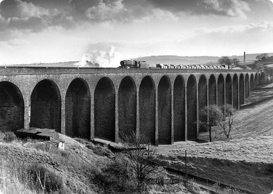
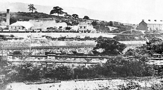
The Whitby, Redcar & Middlesbrough Union Railway was incorporated on 16th July 1866. The maps for the proposed line are much the same as those for that earlier and abortive venture in 1864. From Kettleness to Loftus the line is in the same position as it was upon completion in 1883, but (as in the 1864) maps, there is little indication of any tunnelling or bridging between Sandsend and Kettleness (the map ignoring the topographical problems completely), while the line between (the future site of) Whitby West Cliff station and Sandsend ran further inland than the final construction. The estimate for the proposed line gives the total cost as being £235,278 (a vast underestimation as it later turned out) with £66,100 being earmarked for ‘tunnel and viaducts’. It is unfortunate that the two were not separated in the estimate but we know from later costs that tunnelling was far more expensive than the overall costs of the viaducts. The line in its entirety cost £655,077 [c. £32 million] at £40,942 per mile [c. £1.95 million] and very difficult to construct. Although Parliamentary approval for construction of the line was granted in 1866, the first sod was not cut until 25th May 1871, with John Dickson as main contractor. In all likelihood this hiatus was caused primarily by the difficulties the company had in raising sufficient funds. Nevertheless construction of the line was begun, ushering in one of the most dramatic episodes in the history of branch line building in England. The terrain upon which the line had to be built included ravines of post-glacial streams, the valley sides of which were steep and often unsuited to railway construction except with the use of heavy and expensive engineering works. This terrain, and the difficulties involved in bridging it, is clearly shown in the photographs of Staithes viaduct, while operating costs were heavy, owing to the nature of the terrain and the continuing maintenance needed on the three tunnels and five viaducts along the short 16 mile line.
The viaducts
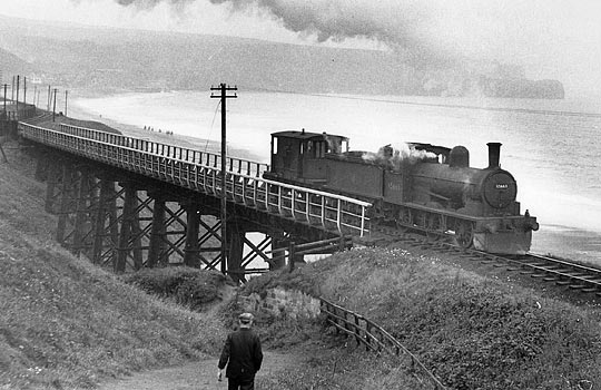
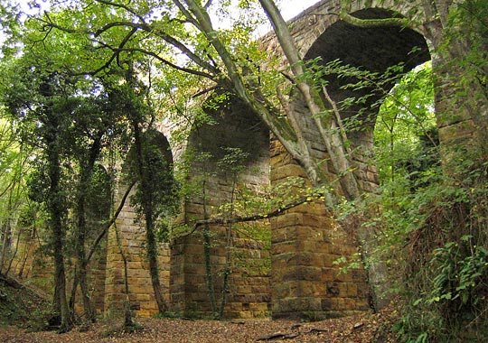
The first of the viaducts in the direction of Loftus from Whitby was at Upgang, about two miles from the commencement of the line at Bog Hall Junction. While there are many photographs of the other four viaducts on the line, those showing Upgang viaduct are hard to come by –
A little further along the line was Newholm viaduct –
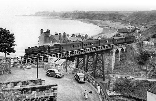
Within half a mile of Newholm was East Row viaduct –
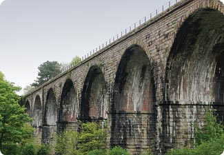
Just to its north was Sandsend viaduct –
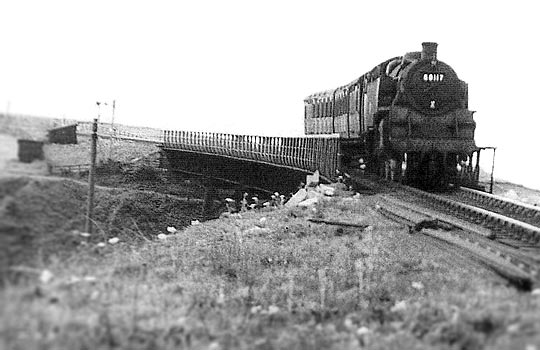
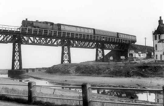
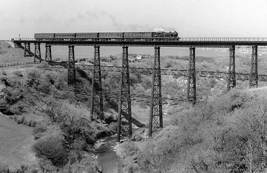
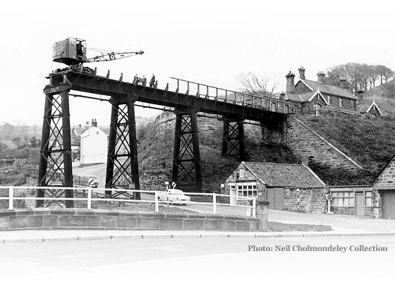
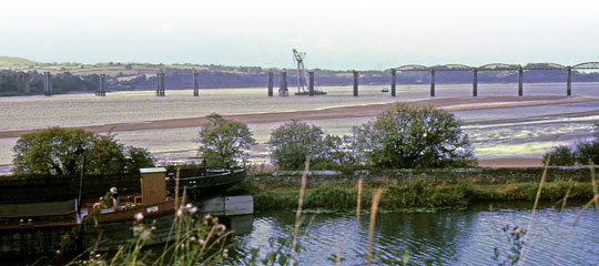
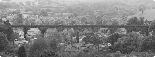
Finally, the pièce de résistance at Staithes –
Photos: Neil Cholmondeley Collection
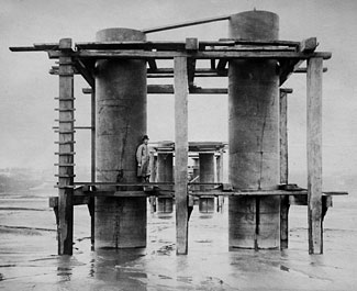
Construction of the viaducts
The viaducts were manufactured at the Skerne Ironworks, Darlington which enjoyed a chequered career: opened in 1864, it closed in 1875 and re-opened twice, in 1876-79 and 1880-82. The designer of the viaducts was John Dixon (not to be confused, as has happened, with the main contractor John Dickson). These contracts (or ‘articles of agreement’) were made on 1st December 1871 and 25th January 1873. The price for the erection of the five viaducts along the line was £23,452 (well over one million pounds in today’s money). The Engineer of 14th March 1873 reported “We have noted with considerable interest the series of viaducts on the new Whitby, Redcar and Middlesbrough Railway, constructed for the company by Mr John Dixon from his own designs but under the superintendence of Mr J H Tolmé, the engineer.
Fortunately, evidence is plentiful for the history of the railway and its viaducts between the years 1871-1889. There are three key sources for the early history of the viaducts with special reference to their cost, the dates of their erection on the line, and the problems they caused before the line could be opened. Arguably the central text is that of the Harrison memorandum which was deeply critical of their design and construction. However, this memorandum was written in 1883, and served to justify the late opening of the line by the NER. The very few historians who have consulted the primary sources accept it at face value; the present historian on the whole agrees with that acceptance.
The viaducts were in place very early in the line’s construction. Unfortunately the contract between Dickson and Dixon has not survived; however, it would have been sensible, and not unusual, to bind Dixon to early completion in order to allow Dickson access along the line. The reports of the Engineer, Tolmé, while not always reliable, provide what seems to be a fairly accurate timeline. His report to the Directors of the WR&MUR company on 9th May 1872 (less than a year after the first sod had been cut) informs them that (between Whitby and Sandsend) “The only heavy work on the section consists of three viaducts, the masonry for which is fast approaching completion and the iron superstructure is now in course of delivery.” On 9th September 1872 Tolmé reported “One iron viaduct on this length (the first seven miles from Whitby) is finished, and two other iron viaducts and two short timber ones are in the course of construction”. The timber viaducts mentioned are of interest for they were to be built on what soon became the abandoned stretch of line around the cliffs between Sandsend and Kettleness.
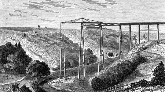
The next five months were productive for, on 21st February 1873, The Engineer reported “The whole of the iron viaducts are now completed, with the exception of the one at Staithes, which is, however, in course of erection.” That this was the case is shown by a most important source, unused by any other historian of the line, which not only gives technical details of the viaducts themselves but includes a vivid and dramatic illustration of Upgang viaduct which, at the time of the publication of the article, can only just have been completed. However, clouds on the horizon were beginning to darken. The Directors’ minutes for 11th July 1873 record that “much discussion took place on the condition and progress of the works and especially with reference to the iron viaducts and the tunnel.
The building of the Upgang viaduct was successful for, in his next report of 1st September 1873, the Engineer, J H Tolmé reported that “One of the piers of the Upgang viaduct, over which trains have been running some time, has been recently weighted with double the maximum working load (viz. 180 tons) and had stood the test in the most satisfactory manner, there being no signs of defect or failure in the slightest degree.” Things were not going entirely smoothly elsewhere for, reported Mr Tolmé on the same date “The work at Staithes viaduct has been almost suspended the last few months pending some slight modifications in the designs of the larger spans. These are now settled, and the work will be proceeded with.” Unfortunately, time was running out for Tolmé and Dickson for, according to the original contract, the line was to be completed within two years “by midsummer 1873” and, by September 1873, that time had passed. In December 1873 Dickson was sacked, and by late 1874 the same fate had overtaken Tolmé.
There are two likely reasons for this state of affairs: firstly, the poor quality of work produced by Dickson of which the Harrison memorandum provides the most compelling evidence and, secondly, the impoverished state of the company’s finances. That these finances were in a very distressed state is made clear in a very important document: a long letter dated 5th May 1874 from Mr Arthur Hamand who had, from May 1872, become joint Engineer with J H Tolmé. Hamand was clearly unhappy with the company and, indeed, while co-signatory with Tolmé to the half-yearly Engineers’ Report to the shareholders of 31st March 1874 does not appear on such a document again, indicating his resignation or dismissal (neither of which are mentioned in the minutes of the Directors’ meetings). In this letter he is severely critical of the company’s financial situation, making clear that the company’s penny-pinching has considerably exacerbated the problems in completing the line.
The sacking of Dickson caused problems for John Dixon, especially as his contracts for the building of the viaducts had been made with the former. Dixon wrote to the Board of the Whitby company on 9th January 1874 stating that “I am now prepared to complete the viaducts according to my agreement with your late contractor John Dickson for the sum of £3,152, being the balance as shown by you, due to me.” He went on to say that the real balance was actually £5,252 “a portion of which has been retained by you in the shape of retentions according to your agreement with him…” These figures indicate that, by early 1874 almost three quarters of the viaduct work had been completed. The Board seemed to acquiesce with Dixon’s demands; the minutes of the Directors’ meeting of 9th February 1874 note that “The correspondence and arrangements made with Mr Dixon for the completion of the iron bridges were read and confirmed.”
In order for Dixon to be paid, the Engineer (Tolmé) had to issue a certificate which had the effect, among other things, of authorising payments to contractors. By March 1874 Dixon was becoming impatient for payment and on the 26th wrote to the Board asking for £1,500. He complained that he had had no certificate since the previous July “…why the Engineer should not issue one regularly every month I cannot understand as it is stipulated for in the contract…the work has been going on continuously”. Nothing happened. John Dixon finally lost patience and on 8th May 1874 sent a very tart letter indeed to the Board, demanding that “your engineer be instructed to do his duty”. It was now nearly a year since he (Dixon) had received a certificate although “I have steadily kept on with the works and I think I am entitled to have consideration”. It is apparent, then, from these letters that although the rest of the work on the line had ceased, work on the viaducts was still continuing. This is confirmed by Tolmé’s last report in that he wrote “…the viaducts on the line have been steadily progressing and are now nearly completed.” What is also apparent is that the Board of the company was in some disarray, caused most likely by the lack of funds.
By now negotiations with the NER to take over the construction of the line were pending. However, it was not until a year later, after the agreement with the NER, that Dixon’s demands began to be met. The minutes of the Directors’ meeting of 20th July 1875 confirm that “…a cheque for £2,000 be paid him”, while the minutes of the next meeting, held on 27th August, 1875 include the resolution that “…a further £1,000 on account of his contract sum of £3,152 be authorised”. Even so, Dixon was not satisfied. The matter dragged on for a further three years until, in September 1878, the minutes of the Directors’ meeting of the 13th declare that “…Mr Dixon’s claim had been settled for £4,500 of the Company’s stock transferred to him.” By 1889, however, this stock had become almost worthless. Nevertheless the viaducts were completed and, to all intents and purposes, John Dixon had (ultimately) been paid.
Before moving to a discussion of the problems presented by the viaducts in the early 1880s, the cost of their construction must be considered. The main source for their cost is the Engineer’s Reports of 1872 and 1873. These reports give (usually at monthly intervals) the amount of moneys spent on various aspects of the line. The costs seem to be cumulative (annually). Thus for 1872 the amount spent on the viaducts was £5,650, while in 1873 the amount spent was £7,500. In today’s money the amount spent on the viaducts in these years is approximately £600,000. These figures are important, for they partly explain why a deviation proposed in 1875 was not taken up. Briefly, this plan was to abandon the section between Sandsend and Kettleness and to construct a deviation inland from Whitby (West Cliff) to Hinderwell. It is possible that it came to nothing because the viaducts would have been rendered redundant and the money spent upon them wasted.
Design of the viaducts
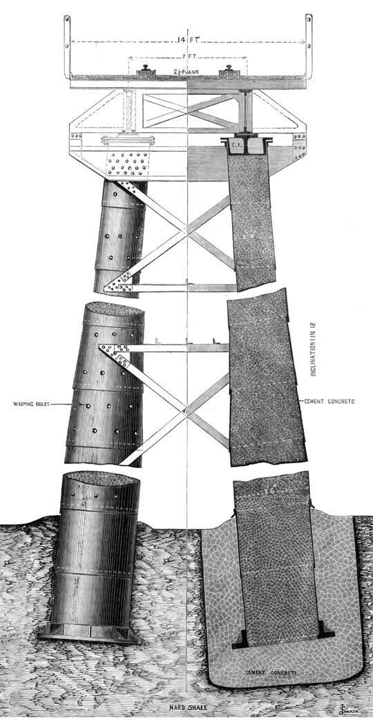
There was a pleasing, if stark, simplicity in the design which was immediately apparent to all those who saw the viaducts while they existed. The Engineer remarked that there was no special novelty in the superstructure, where spans of sixty feet had been adopted. Well-designed lattice girders were thoroughly braced together and these were stiffened laterally by elaborate wind ties were surmounted by cross iron joists which in turn supported a timber platform fourteen feet wide, on which the single line of rails was laid. Because the ravines upon which they were built had at their base shallow streams, there was an equal simplicity in the way in which the foundations of the piers were constructed. The ground was sufficiently solid merely to dig a hole into which the cast iron bed-plate forming the base of the piers was firmly embedded in a mass of concrete. The piers were constructed of wrought iron and The Engineer seemed very approving of Dixon’s idea to fill the piers with cement and concrete, which thus would keep the external skin in shape and dispense with all internal stiffening. “For the sake of concession to popular prejudice more than anything else”, continued the contributor of the article, each pier was equal to a safe load of three hundred tons, more than double that which is theoretically required.
Thus the load was not borne by the iron at all “the real duty of which is to hold the concrete column in shape’. The weight of the column therefore was considerable so the diameter was increased towards the bottom by successive offsets from 2’6” to 3’6” and 4’6” which, for ease of construction, is much preferred to a gradually tapering tube. Finally, weeping holes were punched in the plates at every foot to allow drainage of any excess moisture in the setting of the concrete and each pair of columns is stiffened by diagonal and cross bracing attached to the iron skin of the pier at points duly stiffened to receive it.
As will shortly be noted, it was not the design that was at fault, but the casual and slack nature of the erection of the viaducts which was to cause so much trouble before the final opening of the line on 3rd December 1883.
Illustration from The Engineer magazine (1873)
Delivery of the various components of the viaducts
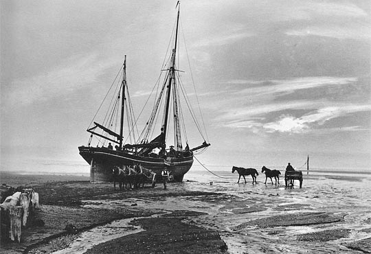
As has been noted above, the viaducts were in place quite early. An interesting question arises: how were they delivered? Manufactured at Darlington, the various parts of the viaducts could have been delivered either by rail or by sea. Similar viaducts, with larger spans, were commonly manufactured at that time in works like Skerne’s, assembled with temporary bolts at the works, dismantled, sent in smaller pieces to sites and reassembled and riveted at the site. If this is the case, then the parts could have been transported by rail to Whitby and then moved by road to the four viaduct sites between Whitby and Sandsend. It is, of course, possible that component parts of the viaduct were small enough for them to have been sent by sea and offloaded by the following method. The well-known photographer Frank Meadow Sutcliffe in c.1887 took a picture of a boat unloading heavy material (coal) on to Sandsend beach, from where it was moved to horse and cart.
Photo: Whitby Literary and Philosophical Society
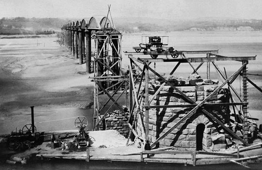
Although the process seems arduous, it may have been the method of transportation for the component parts of the four viaducts, for they all lay very close indeed to the beach where, as seen above, it was possible to ground a boat at low tide. Staithes viaduct, by far the largest of the five, presents a more difficult problem. No material could have been transported from Whitby (Sandsend/Deepgrove tunnel not being completed before 1882) and the nearest railhead was at Loftus five miles away; the Staithes-Loftus section of the line was as problematic as the cliff top section between Sandsend and Kettleness and not completed until July 1878. How, then, was the heavy material transported to Staithes? It can only have been by sea. There was – and still is – a small harbour at Staithes where it might have been possible for ships, carrying the heavy structures, depending upon their size, from Teesside to have landed. While quite a haul through the steep, narrow streets of the village it was not far to the site. A unique visual representation of the construction of Staithes viaduct may be found in a contemporary text. The illustration shows the viaduct being constructed from the southern side of the valley. The piece being manoeuvred into position by the crane seems small enough to have been able to be carried by ship to Staithes. Lacking any primary sources on the matter one can only conjecture, but, using the principles of Occam’s Razor, the sea route seems the simplest method of transportation.
Problems
As already noted, the main source for the history of the viaducts between the takeover of construction of the line in 1875 and its opening in 1883 is the memorandum written by the Chief Engineer of the NER, T E Harrison. It took over three years to remedy the defects in almost every area of construction. Then, when things were beginning to improve, the TayBridge disaster occurred, leading to, inter alia, far greater safety demands on newly built bridges and viaducts. Firstly, in July 1881 a new set of requirements was issued by the Board of Trade which required that the viaducts should be equal to withstanding a wind pressure of 56 lbs to the foot. The viaducts as built were only calculated to withstand a wind pressure of 28 lbs to the foot. Secondly, a further regulation was made to the following effect: “If in iron viaducts the main girders are placed below the level of the rails substantial parapets about 4’6” in height must be provided, and as a further protection substantial guards should be fixed outside, above the level and as close to the rails as possible…” These demands were complied with, but the work was heavy and the cost considerable. Nevertheless by October 1882 the usual notice for inspecting the works with a view to opening the railway was given, and the works were inspected by the Government Inspector, his inspection on that occasion confined to the viaducts, for finding he could not pass them he deferred further inspection on the rest of the line. Far greater detail, however, of this inspection may be gained from the Harrison memorandum. It will be recalled that the designer’s plan was to fill the piers with cement and concrete, but, wrote Harrison, “The Inspector required that in the iron casing of the piers of the Staithes viaduct, holes should be cut in them to ascertain the condition of the concrete with which they were filled, the result being that in the first trial place the concrete was found to be mere gravel without any cement, and with the same result, though not so bad, in several other cases.” This was clearly a disaster, and perhaps argues more forcefully than any other evidence that the quality of the construction of the line under Dickson and Tolmé was appalling, leading Harrison to remark that “It has been asked how it occurred that the Engineer-in-Chief had not discovered these defects before. The answer is simply that he did not believe that such scamping of work could take place with even reasonable inspection, and such a case had never come to his knowledge before.” More detailed inspection at this time revealed that several of the piers were not perpendicular, in one case to the extent of 7”, in others to the extent of 3” or 4”, and this applied more or less to all the viaducts. It was clear that the piers on the tallest viaducts, Staithes and Upgang, had already begun to buckle and remedial work in the form of two rows of longitudinal bracing was necessary. Two rows were, in the end, added to Staithes viaduct and one row to Upgang viaduct. The representation of Upgang viaduct in The Engineer article of March 1873 shows the newly constructed viaduct without such bracing. As well as this, Harrison remarked that upon taking control of the construction in 1875 the roadway for the permanent way on all the viaducts was exceptionally flimsy and all had to be replaced. Specifically, this ‘roadway’ was in the words of The Engineer article, “a timber platform fourteen feet wide, on which the single line of rails was laid.”
When this state of the work was discovered it was, understandably, not thought desirable that any formal report should be made by the Government inspector. Next, it was arranged that steps should be taken for a complete examination of every pier in each viaduct with reference to the concrete, and each pier that was out of perpendicular was with great difficulty straightened. No time was lost in remedying these defects and by aid of a force pump machine designed for the purpose liquid cement was forced into every pier.
It is interesting to note that the inspector was Major General Charles Scrope Hutchinson who in 1878 had inspected – and recommended for opening – the Tay Bridge. According to John Prebble, Hutchinson was “a stiff, scrupulous, exacting man, who had a sharp eye for the inconsequential detail”, and who had only just escaped “the blame, the anger, and the mob-hatred suffered by Thomas Bouch”. The terrible disaster cannot have been very far from Hutchinson’s mind when undertaking later inspections and thus it is likely that he would have made the very highest demands to ensure future safety when inspecting the Whitby-Loftus line. Indeed, after the first inspection in July 1883 Hutchinson concluded severely that “I cannot recommend that the opening of the line should be sanctioned and I must report that by reason of the incompleteness of the works, it cannot be opened without danger to the public using it”. Although not saying so specifically, it was the viaducts which caused Hutchinson the most concern. Hutchinson made twelve requirements to be fulfilled before the line could be opened. Two of these concerned the viaducts: firstly at Staithes viaduct where the longitudinal bracing had to be extended for 3 spans and the ranging of the girders should be as far as possible improved; and secondly, that in all the viaducts the condition of the concrete required careful examination, and means taken to improve it where defective. Not all was bad, though, for Hutchinson concluded that “as regards vibration and oscillation, the viaducts now behave well with heavy engines passing over them at speed.” A second inspection followed shortly afterwards, with Major (later Colonel Sir) Francis Arthur Marindin reporting on 22th August, 1883. But, once again, permission to open the line was deferred; the cause, again, was the defective condition of the viaducts. Indeed, it was clear that the second demand of the previous inspection had not been fulfilled. Major Marindin wrote,
“With regard to [the second] requirement [of the previous inspection], the concrete filling of most of the piers has been found to be very defective and four of the columns in each of the five viaducts were selected by Maj Gen Hutchinson to be dealt with in a manner arranged by him with the Engineer. I examined these columns carefully and I found that, so far as can be judged by sound from tapping the iron casing of the columns, and by inspection at the peep holes and other holes which have been made in the casing, the concrete has now been made good, all the hollow places having been filled up with cement grouting. Orders have been given to continue this work on all the columns, but until all have been satisfactorily healed in the same manner as those which I have tested, I cannot recommend that the opening of this line should be sanctioned and I must report that by reason of the incompleteness of the works, it cannot be opened without danger to the public using it.”
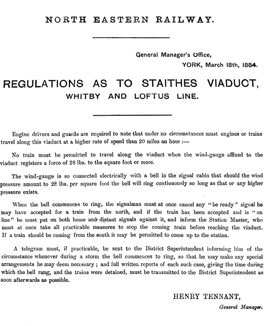
However, at last and two and a half years late, the line was approved by the Railway Inspectorate of the Board of Trade. In the final report, made by of Maj Gen Hutchinson on 3rd November 1883, he gave permission that the line be opened, but it was apparent that he considered that the viaducts still had the capacity to cause problems. On each viaduct the maximum speed allowed was 20mph. Since Major Marindin’s report he found that the concrete in the columns of the viaducts has been carefully gone over, and its defects made good, except in three places in Nos. 5, 6, and 8 piers at Staithes, which were to be at once attended to. He made a number of further demands, firstly that the viaducts be carefully maintained particularly as regards the bracing, both longitudinal and transverse. Secondly, that no time should be lost in painting those portions of wrought iron girders which have not yet been recently painted (this was an ongoing task throughout the line’s history). By far the most unusual demand of Maj Gen Hutchinson was that, at Staithes, because of its height and exposure to easterly gales, a wind gauge should be placed in a suitable position, in charge of the Staithes station master, and that no train should be allowed to cross the viaduct when the wind registers a force of 28 lbs to the square foot or more.
Extremely detailed instructions were issued by the NER three months after the opening of the line concerning the operation of the railway in windy conditions:
Anecdotal evidence suggests that these instructions may, in later days, have been honoured more in the breach than the observance, owing to the inadequacies of the gauge. No doubt there were sighs of relief in both the NER and WR&MUR boardrooms but, as Harrison reminded them just after the opening of the line, “the amount spent in putting the viaducts alone into a proper state exceeded £30,000, but for the work to the viaducts the line would have been completed nearly 18 months earlier.”
Dimensions of the viaducts
In the Board of Trade inspector’s report of July 1883 Maj Gen Hutchinson went into considerable detail when discussing the dimensions of the five viaducts. There was considerable variation in the height and length of the viaducts:
Height (ft)
Max. span (ft)
Girder type
Length (ft)
Upgang
70
60
Lattice
330
Newholm
50
30
Plate
330
East Row
30
60
Lattice (6 spans) Plate (2 spans)
528
Sandsend
53
36
Plate
268
Staithes
152
60
Warren (6 spans) Plate (11 spans)
790
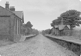
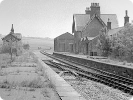
The line opened, beginning its seventy-five year life quietly. As for the viaducts, they initially gave no problems but, by 1895 (only twelve years after its opening) the lattice girders at Upgang viaduct required strengthening and at East Row viaduct complete replacement (owing to corrosion, the viaduct being built actually on the beach and within 35 feet of the sea at high tide). Certain struts on Upgang viaduct had buckled considerably and needed urgent attention while at East Row it was decided to replace the lattice girders with new steel girders. The contractors were the ClevelandBridge and Engineering Company of Darlington. The contract for the Upgang viaduct was entered into on 6th December 1893 and the work finished by 30th August 1894; the contract for the East Row viaduct was entered into on 9th May 1895 and the work was finished by 31st October 1895. The cost of the work reflected the seriousness of the nature of the problems: repairs at Upgang cost £714, while those at East Row cost £2,682.14s.9d. The viaducts were regularly painted and maintained and gave no further problems.
History is silent concerning the viaducts until the announcement by British Railways in September 1957 that the line would be closed, stating that the main reason for closure was the uneconomic nature of the line and that £57,000 would be required for maintenance of the tunnels and viaducts over the next five years. Despite a rearguard action being fought by the Whitby Urban District Council under the leadership of the Clerk, Mr J B McClurg, the line closed to all traffic on 5th May 1958, the last train running on 3rd May 1958.
HL/PO/PB/3/plan 1864/S13 (Scarborough, Whitby and Staithes Railway 1864)
HL/PO/PB/1/29&30 V1 n 250 [Local Act, 29&30 Victoria I, c. cxcv (1866)]
Daysh, G H J, (ed),
A Survey of Whitby and the surrounding area
(Windsor, 1958)
Irving, R J,
The Branch Line Problem in British Railway History
(1993)
Grace’s Guide
The Engineer
magazine (1873)
The National Archives: RAIL 527, RAIL 743, RAIL 1110
Michael Aufrere Williams,
The Whitby – Loftus Line
(Staithes, 2012).
The tunnels and viaducts of the Whitby-Loftus line: Against all odds
Author: Michael Aufrere Williams
Source: Journal of the Railway & Canal Historical Society (No.218)
Published: November 2013
Torksey Viaduct’s battle to enter public service meant overcoming… Opposing Forces
Box-ticking is a fact of life we’re all familiar with. No matter how routine, managerial decision-making is propped-up by paperwork for those rare occasions when investigators need an audit trail to follow. It often seems disproportionate, but such is the shadow cast by our legal system. Nowhere has bureaucracy felt more onerous than in the realm of product approval, justified by the need to avert uncontrolled risk. This isn’t a recent affliction though; those in authority have been rightly asking questions since the railway’s early days.
Box girders are standard design tools for today’s civil engineer and, as such, their history is rarely given much thought. The first major railway structure to employ them – straddling the Nottinghamshire-Lincolnshire border at Torksey – still stands as a notable landmark in time and space. So ground-breaking was it that the regulator initially refused to sanction its use. A vigorous technical skirmish ensued with the engineering fraternity, both sides fearing the reputational damage that being proved wrong might inflict. The result was a four-month stand-off accompanied by mud-slinging.
Grand designs
Largely responsible for development of the box girder was Kelso-born engineer William Fairbairn, working alongside mathematician Eaton Hodgkinson. In the late 1830s, these longstanding collaborators revealed an optimal design for a riveted wrought iron plate beam which, in the context of bridge applications, incorporated cells at the top to help resist compressive forces.
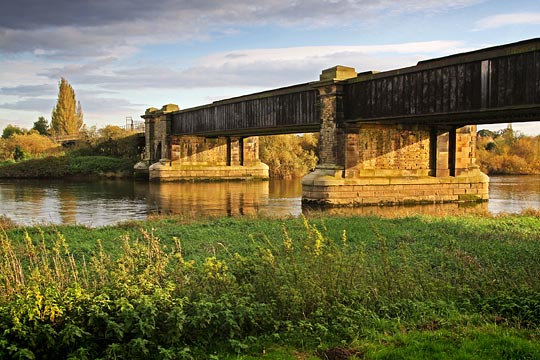
The north side of the viaduct, looking east.
Soon after the pair’s work was published, proposals emerged for the Chester & Holyhead Railway which demanded two substantial bridges, over the River Conwy and Menai Strait. These were advanced under the stewardship of chief engineer Robert Stephenson who put forward the idea of constructing the spans as wrought iron tubes. He retained Fairbairn and Hodgkinson as consultants, asking them to consider the practicalities. In April 1845, a series of experiments began on large-scale prototypes, mostly carried out at Fairbairn’s shipyard in Millwall. Hodgkinson validated the conclusions through calculation.
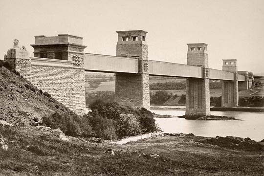
Opened on 5th March 1850, the Menai Strait crossing – known as Britannia Bridge – was a pioneering structure of great proportions. Its two central spans each extended for 460 feet and weighed 1,500 tons; with the side spans, these formed a continuous girder of 1,511 feet, rectangular in section and large enough to accommodate the trains within it. Until then, the longest wrought iron span had been just 31 feet 6 inches.
Ultimately, Stephenson’s tubular girder bridge concept proved too costly for widespread adoption due to the volume – and hence cost – of the materials needed. But it did inspire another engineer to take things in a slightly different direction.
Boxing clever
The Manchester, Sheffield & Lincolnshire Railway established a link between Liverpool and Grimsby through the first Woodhead Tunnel. Its directors enjoyed an inaugural trip between the two ports on 16th July 1849, passing six miles west of Torksey Viaduct which their company was building as part of a line connecting Retford to Lincoln. Engineering it was John Fowler, remembered today for constructing the earliest parts of central London’s underground network and as co-designer of the Forth Bridge.
Crossing the River Trent, the viaduct featured a timber approach structure on its east side – 570 feet in length – with two 130-foot clear spans over the water supported by a central masonry pier. Each span comprised pairs of wrought iron box girders measuring 10 feet high and 2 feet 3 inches wide, with two cells at the top. The deck plates and tracks were carried on cross beams at 2-foot centres.
A shoddy accusation
Work on the viaduct was completed late in 1849 and Captain Lintorn Simmons of the Royal Engineers attended on 21st December to inspect it for the Board of Trade. Formal authority to open was a requirement of the Railway Regulation Act 1840 which brought into being the Railway Inspectorate.
Simmons tested the girders by arranging for two locomotives and tenders to be brought onto each track above one of the spans. The deflection was measured at almost 1¼ inches. This was “more than might, I think, have been anticipated”, he remarked; the riveting “appeared not to be very perfect” and the girders themselves were “not built in a very accurate line, nor very regular in form.” Based on these observations, it was concluded that the structure presented “danger to the public using the same, by reason of the insufficiency of the works.” Approval was therefore refused until strengthening work had been undertaken.
The potential consequences of design and constructional deficiencies were well understood by Simmons, having investigated the fatal collapse of a bridge over the River Dee, one of Robert Stephenson’s lesser structures on the Chester-Holyhead route. It was concluded that the main cast iron girder had been substantially weakened by repeated flexing due to traffic loading. As a consequence, it broke in two places as a train passed over.
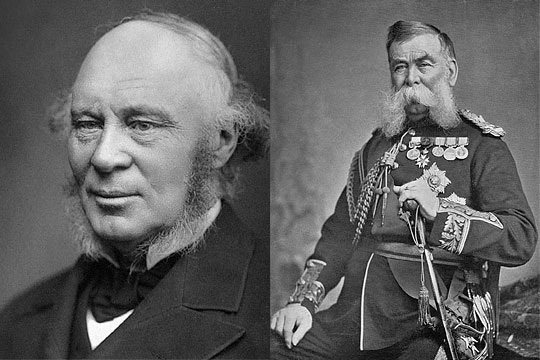
Engineer Sir John Fowler (left) and Field Marshal Lintorn Simmons, the two protagonists in the conflict over Torksey Viaduct.
The accident prompted a government inquiry into the use of iron in railway structures, a substantial contributor being Eaton Hodgkinson who derived an empirical formula for establishing the concentrated load at which a cast iron beam would fail. It was also recommended that such a beam should not be subjected to a live load exceeding one-sixth of that breaking weight.
Unto the breach, dear friends
For the MS&LR, the commercial implications of Simmons’ decision on Torksey Viaduct were obviously damaging. Fowler wrote to him, pointing out that he had erroneously taken the weight of the four locomotives used for testing purposes to be 80 tons when they were actually 148 tons. Simmons recalculated, asserting that “the conclusions at which I before arrived still remain unshaken.” Another trial was arranged, this time resulting in a deflection of 1.26 inches from a load of 223 tonnes (six locomotives), but Simmons would not be moved.
Much indignation was apparent amongst Council members at the Institution of Civil Engineers when the matter was brought before them. Charles Vignoles made it clear that previous “legislative interference” experienced by him had been “extremely obnoxious.” John Scott Russell asserted that “for some time past there had been many attempts to restrict the free exercise of the talent and ingenuity of engineers.” He was especially animated by Simmons’ apparent application of Hodgkinson’s formula “to a new system of construction [wrought iron tubular girders] for which it had never been intended.”
Whilst conducted with appropriate formality, the exchange of letters between Simmons and Fowler had a distinctly prickly tone as each attempted to dismantle the other’s argument. It’s worth making the point – as Simmons readily acknowledged – that neither could claim any expertise as only Fairbairn and Hodgkinson had accrued much genuine understanding of the subject. As such, it became a little like two bald men squabbling over a comb.
On that bombshell
Eventually Fowler cut to the chase, asking Simmons to specify what further strengthening the viaduct needed. He responded that a load of 400 tons over one span – including the 164-ton weight of the structure itself – should not produce a pressure on the top plate of more than five tons per square inch.
Fowler protested strongly at this as Eaton Hodgkinson had, in his view, determined that eight tons per square inch was “a perfectly safe compressive strain”. However Simmons pointed out that this was based on a girder without joints. But Fowler then pulled a rabbit from his hat, claiming that the bridge – without any alteration – already complied with “his extraordinary requirements”, as Simmons had failed to account for the girder being continuous across the two spans. This, according to Fowler, “imparted additional strength to the bridge in the proportion of 9 to 14”. Stumped, Simmons retorted that continuity had “never been urged upon me…as an important element in the consideration of the bridge”, despite “a casual reference” being made to it during one discussion.
Back at the Institution, engineers Charles Wild and William Pole were independently attempting to validate Fowler’s investigations on the benefits of continuity – one through experiment, the other by calculation. They both concluded that as the bottom plate was subject to compressive forces over the central pier – but was in tension elsewhere – the girder could be regarded as three independent beams, divided at the points of contrary flexure. Using this approach, it was determined that the effective length of each span should be regarded as ~108 feet, not 130 feet. With the required load of 400 tons reduced in proportion, the greatest compressive strain on the top plate could then be calculated at ~4.6 tons per square inch, less than the limit stipulated by Simmons.
Offensive retreat
It isn’t hard to imagine the frosty atmosphere when, on 26th March 1850, Fowler, Pole and Wild met Simmons and his colleague, Captain Laffan, on the viaduct to demonstrate their findings. This was done by fixing a telescope to the western abutment, lining up its crosswire to a horizontal mark on the eastern side, then loading one span with nine wagons – totalling 144 tons – and reading off the deflection from a graduated staff. Measurements were taken at 10-foot intervals across the structure and compared with theoretical figures, the largest deviation proving to be just 0.13 inches.
Simmons’ hand had been forced, leaving him with little alternative but to authorise the line’s opening. In doing so, he restated his disagreement with many of Fowler’s observations and, as a parting shot, insisted that the depth of ballast over the viaduct must not exceed two inches in order to minimise its loading.
Charles Manby, Secretary to the ICE, voiced the profession’s collective displeasure at the four-month “arbitrary” closure imposed by Simmons, condemning “the employment of officers who possessed undoubted skill for their own peculiar military duties, but who were placed in a false position when they were entrusted with the execution and control of civil works.”
Different times
All this proved a momentary distraction for Simmons. Three years later, whilst on leave in Turkey, the British Ambassador requested that he report on the country’s ability to resist a Russian advance. Then the Crimean War started. In 1854, he became British Commissioner with the Turkish Army, playing a prominent role in several battles. His distinguished military career culminated in promotion to field marshal in 1890.
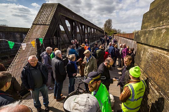
The viaduct’s Pratt truss dominates the scene at the footpath’s opening ceremony.
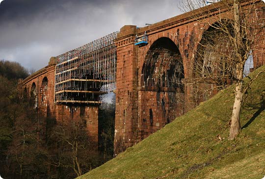
An evolution had changed the face of Torksey Viaduct by the turn of the 20th century. In 1877, the timber approach structure was replaced by cast iron screw piles supporting wrought iron girders whilst, 20 years later, the main spans were stiffened by moving the southern girder outwards to create space between the tracks for a pair of Pratt trusses. How telling is that?
A train last tested Fowler’s work in 1959. Closure brought deterioration with it and, despite a Grade II* listing, the structure recently found itself on the Heritage at Risk Register. However two £200,000 grants from the Railway Heritage Trust paid for Hankinson Group to grit-blast and repaint the north-side ironwork in advance of a footpath being laid over it by Railway Paths, the viaduct’s current custodian, and Sustrans. This was formally opened in April 2016.
Further afield, Britannia Bridge was damaged beyond repair on the evening of 23th May 1970 when two boys – playing inside it – dropped a burning torch and set alight the tar-coated timber roof. It was rebuilt to an arched design by Husband & Company, later acquired by Mott MacDonald. Rail traffic resumed in January 1972. Stephenson’s other tubular girder bridge over the River Conwy continues to carry trains on the North Wales coast line.
Regulators have a duty to challenge innovators, but don’t have the right to stifle them. When it came to box girders, officialdom was overcome by the great Victorian engineers who wielded considerable clout; too much of it perhaps. Today the tables are turned, driven by an institutional fear of the unknown. The extent to which that disadvantages the industry as it strives to reduce costs and improve efficiency is something that should be determined. Did Hodgkinson have a formula for that?
Torksey Viaduct's battle to enter public service meant overcoming... Opposing Forces
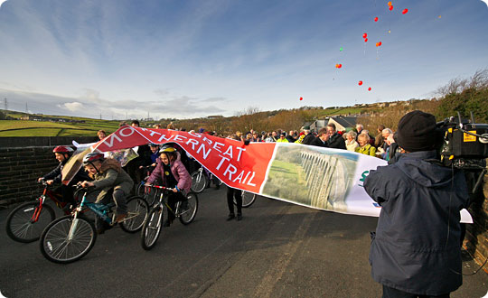
Thornton reopens as traffic-free route
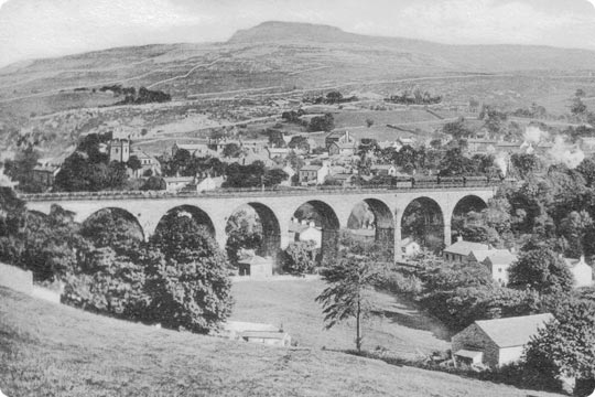
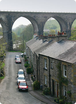
West Yorkshire’s iconic Thornton Viaduct has reopened for the first time in nearly half a century, but for walkers and cyclists rather than trains.
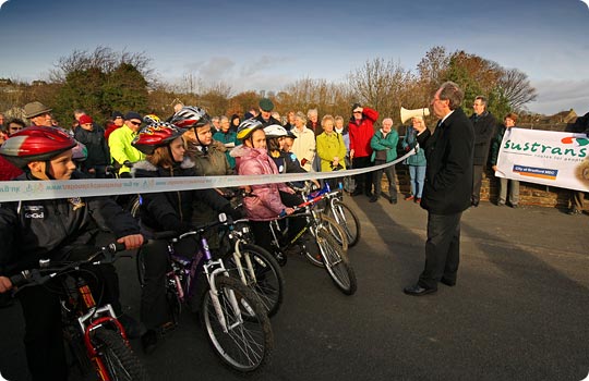
Children from Thornton Primary School, which occupies the site of the village’s former station, were excused lessons to join the official celebrations whilst local historian Alan Whitaker, son of Thornton’s last station master, addressed the gathered crowd.
Alan Whitaker, son of Thornton’s last station master, addresses the crowd before the viaduct’s official opening.
The third section of the Great Northern Railway Trail crosses the viaduct. When linked together, they will create a picturesque, traffic-free route linking Queensbury and Cullingworth, mostly along the trackbed of a heavily engineered line known by locomotive crews as ‘The Alpine Route’. Built between 1876 and 1884, it was characterised by deep cuttings, high embankments, tunnels and wonderful viaducts. Closure came in 1965.
Sustainable transport charity Sustrans is developing the trail in partnership with Bradford Council and the Great Northern Railway Trail Forum, a consortium of supporting local organisations.
David Hall, Sustrans’ Yorkshire Regional Director, said “The local landscape at Thornton is quite outstanding. Many people had no idea of the dramatic views across the valley which are now accessible to people as they stroll or ride along the railway trail.”
Children from Thornton Primary School are first to enjoy the new route.
The new half-mile section of the trail took four months to construct and the entire six-mile project is expected to be complete by 2011. Thornton is one of two Grade II listed viaducts on the route, three miles of which are now open.
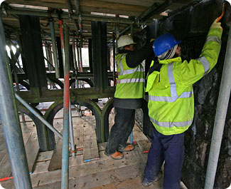
Richard Murphy recounts his lone quest to protect Slapewath Viaduct: Getting a structure listed
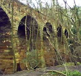
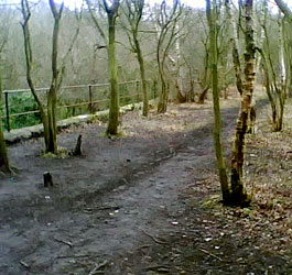
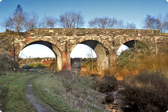
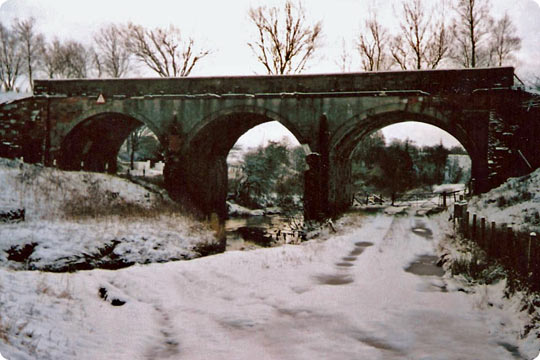
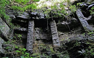
This is a story that started back in the early Noughties and culminated in what is probably one of the proudest moments of my life. I had no interest whatsoever in railways until one day I happened across an old viaduct, set amongst dense trees alongside the main road south-west of Slapewath in North Yorkshire. My first visit was very short as I was out mountain biking with my friend Craig who doesn’t appreciate long stops. It was a warm June day and all I remember is glimpsing stone arches above a stream. “Next time”, I said to myself, “I’ll walk over and have a good look at that.”
Months went by. But walking past it on my way to Guisborough one day, I had some time and examined the whole structure. I took photos on my old phone, turned off the road, down through the bushes and up to one of its piers. Then it happened. I climbed up the eastern end and onto the deck. There I saw trees growing over the handrails and roots displacing its stonework. I found myself consumed by an incredible sense of injustice.
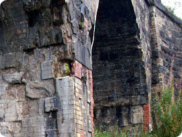
Two of Richard’s original pictures……taken on his old camera phone.
I’d never given a moment’s thought to my local history or the railway and ironstone mining heritage thereabouts. But it surrounded me and played such an important part in the industrial revolution. I walked the viaduct’s length, not understanding why trees had been allowed to grow on top of it; why such a mysterious structure was in such a state. I came back down at the western end and, placing a hand on the first pier, said to myself “we’ve got to find a way to keep you.”
From that day until December 2011, preserving this beautiful, once vitally important but now neglected piece of industrial heritage was never off my mind. Never. Every email, every hour spent poring over dusty books in the library, squinting at old OS maps, typing and re-typing keywords into search engines, then spending hours sifting through the results and the websites beyond ‘til my eyes refused to focus anymore. The anxiety about whether I would be too late – would I go back one day and find it demolished? The mesmerising wealth of information on the ironstone industry and the railways that once serviced it – all now long gone from the landscape. The excitement of receiving replies from people who shared a common interest and using the information within to enhance both my personal knowledge and my application to get the viaduct listed. And the email I eventually received from Peter Rowe of Tees Archaeology, informing me that I’d been successful: that was the best feeling of all. Ever.
This is how I achieved it.
History of the Cleveland Railway
The Cleveland Railway in north-east England ran from Normanby near Middlesbrough, via Guisborough through the Eston Hills, to Loftus in East Cleveland. It carried minerals from numerous iron ore mines along its route to the River Tees for shipment to Tyneside and elsewhere. The line was an offshoot of the West Hartlepool Harbour and Railway on the north bank of the Tees, to which it had a cross-river connection via a jetty at Normanby. It was built as a freight line and provided no passenger services during its brief existence as an independently owned railway.
The route was progressed in a number of stages, bypassing the centre of Guisborough, and opened in November 1861. Its construction was repeatedly held up by disputes with its main rival, the Stockton & Darlington Railway, which unsuccessfully attempted by every means at its disposal to maintain its rail monopoly south of the Tees. However, the Cleveland Railway remained independent only until 1865 when the company and its rivals were bought out by the North Eastern Railway.
An 1894 map showing the various lines at Slapewath, with the viaduct labelled to the left of Slapewath Junction.
The new management linked the line with an existing coastal route via Saltburn, running north of the Eston Hills, and closed the line west of Guisborough in 1873 after only 12 years of service. The NER also constructed four passenger stations at the eastern end of the line in the 1870s. These were closed between 1958-1964, along with the section of line from Guisborough to Brotton, but the easternmost part is still in use today for mineral traffic.
Click here for more information.
Why did I want it listed?
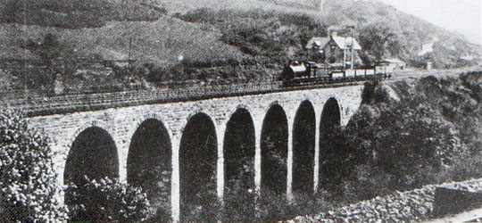
I started off determined to preserve Slapewath Viaduct purely as a piece of history, one that very few people left alive have ever heard about, let alone seen. Most people who travelled over it as passengers on trains are over 60. To have clear memories of 1960 you’d have to be born by 1950.
Every time I mentioned it to someone, they didn’t have a clue what I was jabbering on about which I found the most infuriating part. To me, I’d found a beautiful historical relic and wanted everyone not only to know about it but also to see it. People – including my girlfriend at the time – just smiled, said “great” and then gently changed the subject. It felt like it was just me and my viaduct against a world filled with indifference – neither my friends nor ‘the powers that be’ seemed to care about it at all.
Why didn’t the Cleveland Way go over it? Why was it in such a state? Why wasn’t it easily accessible to the public? The only people who used it were abseilers and the occasional walker who saw the public footpath sign at nearby Fancy Cottage and took the chance. Even the cycle path from Guisborough came to an abrupt end just before Spawood Junction and diverted riders onto a cycle path alongside the A171 which didn’t seem to make sense or be very safe. Why? I started asking questions and searching the internet.
The first organisation I contacted was the Northern Viaduct Trust. Just a general enquiry about what I had to do regarding the process of preservation. Mike Sunderland was absolutely brilliant and not only replied with a comprehensive checklist of what I should do next, but also a description of how they had preserved all of their structures near Kirkby Stephen. The insight from that one email was enough to fire me, not only in the right direction but also exactly what to do along the way. Check out the NVT’s website for some truly stunning viaducts.
From there I set up a Facebook page, Friends of Slapewath Viaduct (requires Facebook account), which I used to post photos and generate discussions. Friends joined, some gave me information but generally it was to focus my thoughts on the job in hand. Emails to my local conservation officer, Graeme Bickerdike at Forgotten Relics, Sustrans, English Heritage and the like, led to other people giving me additional, valuable information. Ownership, date of construction, date of closure among other issues were discussed and, in the majority of cases, resolved.
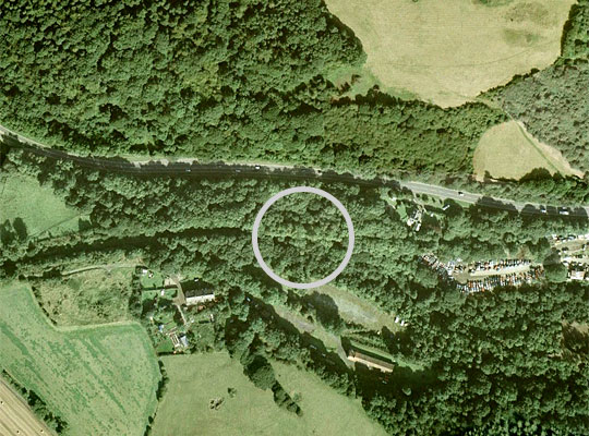
The viaduct is not visible on aerial photography but can be located by the line of lighter coloured trees in the circle. Photo: GoogleEarth/The Geoinformation Group
Research turned up an incredible history of how the railways spread from Middlesbrough all the way over to the mines in East Cleveland. Finding out that Guisborough once had two competing railways, using two different routes with one crossing the other behind what is now the town’s sorting office, was at times difficult to comprehend. The when, why and hows took a long time to sink in. It’s too long to recount here but the battle between the Cleveland and the Middlesbrough & Guisborough railway companies during the mid 19th century are both fascinating and, sadly, little known about. Well worth researching though if you live within 10 miles of Guisborough!
The most interesting research turned up the structure of the Cleveland Railway in the vicinity of Slapewath and Spawood mine. The realignment of the A171 in the late 20th century had obliterated the old road; the bridge to Skelton pit was demolished before the Second World War and the road bridge over the lines actually in Slapewath was buried and now forms part of the Cleveland Way adjacent to the shale quarries on the north side of the A171. The cat’s eyes in the path are all that remain to remind walkers of its use as the main road between Guisborough and Whitby.
How did I get it listed?
The process started by downloaded forms from English Heritage’s website. They are easy to fill out. If you’ve done your research and know all there is to know about the building or structure, fill in the basics in legible handwriting, print the additional information out and attach. Write a full and accurate description of it and as many valid reasons why it should be preserved. Saying it looks nice or the place won’t be the same without it probably won’t work.
My argument was that of all the railway viaducts in East Cleveland, Slapewath is the only surviving one of stone construction and was built between 1858-62, long before the Whitby Redcar & Middlesbrough Union Railway viaducts between Loftus and Whitby. Kilton Viaduct was buried under mine spoil around the turn of the century after subsidence, whilst those at Staithes, Sandsend, East Row, Newholm Beck and Upgang were sold for scrap in 1958-1960. The nearest stone viaduct would have been Thorpe Thewles but, guess what, it was blown up in 1980. The only one left is Saltburn Viaduct which is brick and still operational.
I also included a land registry search, current OS map with grid reference and an old map taken from one of the many mapping websites. Obviously the location of the viaduct was highlighted together with the relevant junctions. An aerial view from Google Earth also showed its position but the viaduct is obscured by trees. All good for reference though.
Built in 1858-1862 as part of the Cleveland Railway, Slapewath Viaduct ran over Spa Gill as the track passed through Spa Wood to transport ironstone from local mines such as Spa Wood, Skelton Shaft, Skelton Park Pit and Waterfall to Normanby jetty on the River Tees at and the furnaces alongside.
Amalgamated with NER about 1863. Closed on 30th April 1960. Last train was on 2nd March 1964 which was an inspection by the Chief Civil Engineer to Teesside.
Bridge number and dimensions are GUH1 Br No 7 @ 10m 63ch. It is 20 metres south of the A171 (Fancy Bank) slightly left of a car recycling business. It is easy to spot because the strip of trees on the bridge deck is a different colour on an east-west axis.
Ownership
Slapewath Viaduct (engineers reference GUH1/7) was sold to Mr & Mrs Frankland-Jones by BRB(R) on 12th September 1972. There was a Frankland-Jones on the Electoral Roll in Guisborough in 2002 but after then there is no record.
Charles Morris, Chairman of the Cleveland Industrial Archaeology Society, through third-party correspondence thought it was most likely to be part of Lord Gisborough’s estate but others have inferred that it may be owned by Skelton & Gilling Estates. Enquiries to both proved fruitless.
I contacted Redcar & Cleveland Borough Council regarding land ownership and they confirmed it was not theirs but unfortunately had no record of the owner. Stewart Ramsdale, R&CBC Conservation Officer, wrote –
“Dear Mr Murphy
I understand from my engineering colleagues that notification of demolition of the viaduct would not be required. The notification/approval system apparently applies to buildings rather than structures.
I also understand that while the notification system is in the public domain, and therefore accessible to members of the public, there is no requirement to publish notifications. This is probably because the system relates to public safety rather than a concern for buildings.
Good luck with your endeavours.”
An enquiry through the Land Registry also provided little information as the 13 properties listed were cottages, farms and one saw-mill. Other enquiries merely stated that the land was freehold either side of the Whitby road in the general location of the structure.
It also seems, apart from approximately 20-30 assorted photographs, no-one has published a history of the structure. Even less in evidence is anything regarding the bridge that at one time crossed the Whitby Road to Skelton Park pit, the junction of which has remains adjoining the eastern end of this structure.
Please find enclosed numerous photographs taken this year of both the structure’s exterior and the condition of the deck, a Google Earth photo with the approximate location of the structure highlighted and an OS map excerpt from 1926 showing the old alignment with coloured box to show the position of the structure and also the aforementioned Land Registry enquiry.
Claims to special architectural and historical interest
It is over 150 years old.
It is the only disused viaduct of stone construction in East Cleveland remaining. Larpool and Skelton (both listed) are constructed of brick.
There are bridges further to the west which form part of the structure of the disused railway between Guisborough and Boosbeck that have been listed. They would seem to be architecturally inferior and of less historical interest.
Slapewath Viaduct has a very important place in the history of both ironstone mining and the development of the railway network in East Cleveland. Except for the two structures above, all the rest have been dismantled or are in a very poor condition. Upgang, Newholm Beck, East Row, Sandsend and Staithes viaducts were sold for scrap 50 years ago and the tunnels at Sandsend and Kettleness are in a very poor condition.
I hope this application is satisfactory as this wonderful structure caught my imagination a few years ago and is never far from my thoughts. It would be a great loss, not only to the people of East Cleveland today but for future generations, eager to learn how Cleveland ironstone was transported to the Tees and therefore how Gladstone came to describe Middlesbrough as an ‘Infant Hercules’.
Yours sincerely
Richard A J Murphy2nd September 2010
Problems encountered
The main problem I encountered was determining the structure’s owner. Numerous emails, books and websites returned no useful information in this regard. The one stroke of luck was Graeme at Forgotten Relics who did some research and turned up the BRB(R) information regarding it being sold to Mr & Mrs Frankland-Jones in 1972. Even English Heritage had initial difficulties but they must have discovered the information in the end.
Access was limited as rights of way were confusing to say the least. During numerous visits over the past few years the only people I ever saw were on trials bikes. Hopefully that should change in the future.
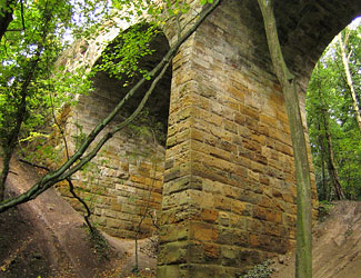
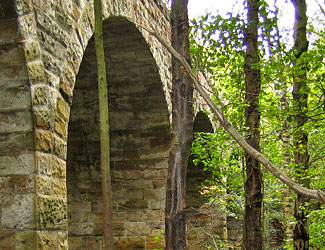
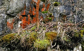
Much of the stonework remains in fair condition… …but photographing the viaduct is difficult due to the trees that surround it. Photos: Richard Murphy
Trees hindered photographing the structure. Even in winter, without their leaves, the surrounding vegetation made long range photography very difficult. Maybe in the future, if the viaduct is cleared, this might also be thinned but hopefully not to the extent of encouraging erosion by both water and people enjoying the view.
It was a long walk! I live in Marske so it is a long way via Tocketts Mill, Mucky Lane and Waterfall corner, especially during inclement weather. Seeing the viaduct in the trees made it all worthwhile.
Research materials
In all the years of my limited research I found no more than 30 photos of the viaduct. The main source was my own pictures taken at different times of the year.
Books, the internet, map websites (especially New Popular Edition (NPE)), Google Earth, Wikipedia, NER Encyclopaedia and the National Archives in Kew all proved invaluable. A very useful website is Closed Stations, part of the Subterranea Britannica site. I spent hours looking at photos of how the local lines and stations used to look. Incredible stuff!
It also unearthed other lines at Cod Hill Junction, Upleatham Junction and of course the least known railway of all which is Paddy Waddell’s – the proposed line from Moorsholm to Lealholm which was never built at the end of the 19th Century. I only found one book that described this route.
Sources of opposition
Friends and colleagues were the worst – no interest at all really! The council was uninterested and Sustrans proved helpful at first – asking to schedule a meeting – but then nothing.
I wonder what the owner thinks?
Personal reflections
Did I ever feel like giving up? No, never. After the application went in, the main cause for concern was that it would be turned down. Day after day looking in my Inbox for anything from English Heritage didn’t help feelings of anxiety. If it had been pulled down after I’d walked away I would never have forgiven myself.
Would I do it again? Yes, hopefully this year. I’m just deciding what I’d like to preserve. Crimple Low Viaduct in Harrogate looks a possibility. It might be disused and a bit creaky but it’s a spectacular structure – everyone raves about the nearby Crimple High Viaduct but overlooks Crimple Low, which is unfair.
Would I advise others to do the same? Absolutely – do it right now! Get down to your library’s Local History section and do some research. Download the application forms from English Heritage and crack on. You won’t regret it.
Richard’s efforts should ensure that Slapewath Viaduct will be protected for future generations to marvel at. Photo: Richard Murphy
A chance encounter with a hidden, neglected piece of history – and a great deal of help from friends and acquaintances – not only instilled pride about where I live but it also changed me as a person…for the better. Photos of Thorpe Thewles Viaduct will always remind me why I did this. Once it’s gone, it’s gone for good.
Richard Murphy recounts his lone quest to protect Slapewath Viaduct: Getting a structure listed
The story of the Severn Railway Bridge: Lost in the fog
For business or for pleasure, through need or curiosity, daily life generally entails some form of travel. Anyone employed by the railway can be thankful of that fact. Rarely though do journeys live long in the memory – your eventual destination being the real draw. But what if you never get there? What if fate intervenes? Fifty years ago this month, George Thompson and James Dew set out on separate journeys that would have appalling consequences for five of their colleagues and one bystander – a piece of spectacular railway engineering.
Frenzied development
Taken on 27th January 1877, this shot shows the construction of piers 12, 13 & 14 and is from a fabulous album of construction photographs held at and reproduced courtesy of the Gloucestershire Archives (Ref B417/23554).
Today, those robbed of daylight as their train plunges beneath the river between Severn Tunnel Junction and Pilning probably don’t think twice about the engineering of that four-mile black hole. Neither will they care that it was not the first attempt to link the Severn’s west and east sides with a tunnel. Work to extend the Bullo Pill Railway through to Arlingham had reached the river’s midpoint when, on Friday 13th November 1812, an inrush of water flooded the excavation, leading to its abandonment. All lives were thankfully spared.
But the network’s development through much of the 19th century, coupled with the financial rewards to be reaped from South Wales’ colossal coal reserves, were to spawn an abundance of similar visions. None was more audacious than Brunel’s 1844 proposal for north and south-facing bridges – each around 800 yards in length – forming part of plans for a line linking London with South Wales, crossing the water eight miles south-west of Gloucester. The city’s businessmen, alive to the commercial impact of being bypassed, mounted a vigorous and ultimately victorious campaign against it, securing the route still in use today.
The drawing board remained busy with six proposals emerging in 1871 alone. Included within this collection were the Severn Tunnel Railway and the Severn Bridge Railway No.2. The former navigated its parliamentary passage in August 1872, welcoming a trial goods train on 9th January 1886. At its peak, 3,628 men laboured on it. The latter would also come to fruition but those who paid for it probably wished it hadn’t.
The pier cylinders and temporary staging pictured on 24th March 1876. Photo: Gloucestershire Archives (Ref B417/23554)
Conflicting interests
On 16th June 1876, a group of workers take a break during the construction of spans 2 & 3. Photo: Gloucestershire Archives (Ref B417/23554)
Engineered by George William Keeling and George Wells Owen, the four-mile Severn Bridge Railway formed a junction with the Severn & Wye and South Wales railways at Lydney, then disappeared into a tunnel of 506 yards before climbing onto the bridge to cross the water. At the east side, it joined a branch of the Midland Railway at Sharpness Docks.
Powers were taken to raise its £278,000 estimated price tag. The Severn Tunnel, which had also been granted Royal Assent, was likely to cost three times as much. Although the distances between London and South Wales via the two routes were comparable, the bridge benefited from gentler gradients; this lulled the company’s directors into believing that they would secure the lion’s share of that lucrative coal traffic.
Running powers over the route had been granted to both the Midland and Great Western railways – they could exercise these through investments of £50,000 in the project. But their conflicting interests brought much delay, eventually demanding mediation. When decision-makers found against it, the initially-supportive GWR walked away to focus its attention on the tunnel.
Bickering and financial navel-gazing gave way to physical progress on 3rd July 1875 as company chairman W C Lucy laid the two-tonne foundation stone. Hamilton’s Windsor Iron Works Co was awarded the £190,000 contract to erect the bridge whilst Vickers & Cooke – later to be replaced by Griffith Griffiths – was tasked with delivering the remaining structures and stations, work valued at £90,000.
Assembly in situ
On 8th May 1877, work on the masonry support for the swing bridge is making good progress. Photo: Gloucestershire Archives (Ref B417/23554)
This was a venture of enormous scale and complexity, made all the more formidable by the Severn’s great tidal flows. 4,162 feet in length, the bridge consisted of two spans of 327 feet over the main channel, with 19 lesser spans and a swing bridge at its eastern end across the Gloucester & Berkeley Canal. The western approach was carried on a 13-arch masonry viaduct – no mean feat in itself.
The pier columns were formed of 4-foot cylindrical sections, 10 feet in diameter. The first dozen piers had to be sunk through 28 feet of sand before bedrock was found. Extensive staging was assembled from which the cylinders were lowered on chains bolted to the inside flanges. Felt-lined to deal with expansion, they were then filled with concrete. A primitive piling machine helped to drive the sections through a clay ridge close to the east bank.
A 10-knot tide rising 30 feet in a little over two hours precluded on-shore construction of individual spans prior to them being floated into position. Instead the staging was extended upwards to allow assembly of the ironwork in situ. This operation attained such efficiency that many of the spans were erected in a week, with bolts used as a temporary fix before the riveters came along to provide a permanent one.
The greatest challenge – that posed by the navigation channel – faced engineers in the autumn of 1878. Initial efforts were thwarted by the tide which washed away the staging and several pier cylinders; massive timber piles were snapped at their base. But the following February brought the first span’s completion. Work on the second benefited from floodlighting, making the introduction of a night shift possible, and reached its conclusion in August. Eight locomotives took part in rolling load tests, deflecting these spans by just 1½ inches. Their construction did though claim the life of workman Thomas Roberts who plunged into the river from deck level, a distance of 70 feet, striking the staging on his way down.
Crowds gathered at every vantage point to witness the first public train rumble over the structure on 17th October 1879. On its return run, a detonator was exploded on each of the 21 spans. After crossing again, passengers got off to accompany W C Lucy onto the bridge where he ceremonially tightened the last bolt. What would the HSE have said? It was an act of great symbolism, not least because 24 hours earlier The Great Spring had penetrated the Severn Tunnel’s top heading, flooding the workings to river level. No progress was made there for over a year.
Brace yourself
A view along the bridge from the west side of the river. Photo: Brian Hillier
But any sense of smugness was shortlived. Expected traffic levels failed to materialise and the company’s financial resources were drained further by the Severn & Wye Railway – a servant of the Forest of Dean’s ailing coal industry – with which it had amalgamated in 1878. Losses were cut in 1894 when, with most trains heading for the now-open tunnel, the company was transferred to the Midland and Great Western, under the control of a joint committee. The bridge was effectively bankrupt.
In 1955, a detailed examination prepared the way for heavier locomotives to use the structure, providing an alternative route from South Wales to Bristol. The following year, with strain gauges installed to record the deflections, a series of tests was carried out involving two Castle-class locomotives, eight loaded Grampus wagons and a brake van. The outcome was a £125,000 contract let to Fairfields for the strengthening of almost 500 diagonal braces.
Work got underway in 1960, with the firm afforded a nightly possession of the bridge after the last train had passed over at 2145. By late-October, three spans were complete and scaffolding encased a fourth. But suspect ironwork was soon to be the least of the bridge’s problems.
On 19th October 1956, ex GWR 0-6-0PT 1639 crosses the bridge. Photo: Brian HillierThe view looking west from the signal box on the swing bridge. Photo: Brian Hillier
Power of the tide
Calm greeted James Dew, skipper of the Wastdale H, as he eased his vessel out of Avonmouth Docks at around 1915 on the evening of Tuesday 25th October 1960, embarking on the return leg of a journey that had begun in Worcester early that same morning. Travelling with him was a crew of three and 351 tonnes of petroleum spirit. Slightly ahead, he could see the lights of tanker barges which had sailed up from Swansea on the afternoon tide. Amongst them was the Arkendale H, loaded with 296 tonnes of Britoleum fuel oil and captained by George Thompson.
Although visibility was good, the area around Berkeley Power Station – three miles downstream of the bridge – was notorious for thick fog, a function of cool air blowing over the sun-warmed foreshore. And so it was that evening – by 2200, 16 craft were enveloped.
As he passed the power station, Thompson swung his barge around to stem the tide, punching into it at such a rate as to overcome its power. As he reached the piers at Sharpness marking the entrance to its docks, a tug towing several barges crossed his bows, forcing him to kill the power and drift upstream. As he lined up for a second attempt, the Wastdale H emerged from the murk on his port side. On board, Dew was fighting the tide and his ignorance – this was only his third day on the river.
As they came together and unknown to either skipper, a crewman on the bow secured a line between the vessels. They were now inseparable. Thompson and Dew battled to prise their craft apart but succeeded only in losing control of them. Caught by the fast-flowing current, they were pushed upstream towards the bridge. Travelling sideways, the Wastdale H slammed into Pier 17, turning the vessel over. The Arkendale H ended up on top of her. As Thompson emerged from his wheelhouse, the pier and the two spans it supported fell onto the stricken craft.
A police officer surveys the damage the morning after the night before. Photo: Press Association
Mounting the rescue
Supervisor T C Francis left the signal box at Severn Bridge Station, on the western bank, at 2230. As he walked down onto the bridge, a sheet of flame burst skyward; an explosion followed. He ran back to the box to call the emergency services. On his return, he was confronted by a hole where once there were girders. Still burning fiercely and burdened by the collapsed spans, the barges were carried upstream before grounding on a sandbank.
Thompson had been struck by flying debris and lost consciousness for a time. Once revived, he found his mate Percy Simmonds and engineer Jack Cooper on the stern. Knowing that neither could swim, he gave each of them a life belt and instructed them to jump. He did, they didn’t. With the river ablaze all around him, Thompson had no choice but to swim for survival.
Dew too was in the water. He clambered on board the Arkendale H where he found the two men wondering what to do next. They had already inflated a life raft but it drifted away. Dew led them onto the deck from where they walked into the water. Cooper was swept to the stern of the vessel and caught by its still-revolving propeller. He was eventually rescued. Remarkably, Dew was found uninjured three hours later, upstream of the bridge. The tide carried Thompson for three miles before depositing him on the bank.
The remaining crewmen – Simmonds (34), Jack Dudfield (46), Alex Bullock (40), Robert Niblett (25) and Malcolm Hart (17) – all succumbed.
The collision resulted in the loss of Pier 17 and the two deck sections supported by it. Photo: D J Norton A view of the damaged bridge from Purton on the river’s west bank. Photo: John Thorn
Accident prone
The fate of the bridge was engulfed by protracted debate. Rebuilding costs were estimated at £312,000 against £250,000 to dismantle it. Local opinion favoured the former as the structure provided an important community link, particularly as the children of Sharpness took the train to and from their school at Lydney on the opposite side.
In December 1961, an underwater survey discovered extensive damage to Pier 16 which was leaning towards the east bank. A contract was awarded to erect a temporary trestle, eliminating any danger of collapse. Days before work started, an upturned tanker drifted into Pier 20 on the ebbing tide, causing a further £13,000 worth of damage. This same pier was again the victim when the contractor’s twin-hulled crane broke from its moorings; the deck’s underside was also struck by its jib. The bill on that occasion was £6,000.
By 1965, British Rail wanted only to cut its losses, having received just £5,000 in compensation for the original disaster. Twenty-four companies were invited to tender for the demolition work; 20 withdrew their bids following a site visit. Nordman Construction – not one of the remaining four – got the job.
Demolition of the bridge involved a floating crane, the Magnus II. Photo: Press Association
On Tuesday 22nd August 1967, a huge floating crane, Magnus II, was piloted up the Severn. With a propeller at each corner for maximum manoeuvrability, it boasted a lifting capacity of 400 tonnes to a height of 150 feet. When she left three weeks later, the swing bridge, three spans and 21 piers were still standing. It was not until 10th March 1968 – three months after the deadline – that another company, Swinnerton & Miller, finished the job with explosives. It was another two years before the debris was cleared.
A group of workers assist in the bridge’s dismantling. Photo: Press Association Debris from the demolition littered the Severn until 1970. Photo: Peter Coleman/ TammyLynn Photography
Mighty bridges
Whether to go under, over or around was the conundrum posed by Britain’s great rivers when the railway reached their banks in the 19th century. In meeting nature’s challenge, engineers crafted mighty bridges. Whilst the Forth, Tay, Royal Border and Royal Albert continue to shine, the Severn’s lost crossing stands alongside them, if obscured by the mists of time.
Viewed from above the Gloucester & Berkeley Canal, the Magnus II worked its way along the bridge, removing the deck sections. Photo: Graham EdgeworthRemaining ironwork from one of the western piers tries hard to keep its head above water. Photo: Midland Explorer Boy The central support for the swing bridge also survives, together with some of the masonry approach viaduct at the eastern end. Photo: Midland Explorer Boy
Information about the resources available via the archive.
The story of the Severn Railway Bridge: Lost in the fog
The story of Mosshouse Viaduct’s demolition: Going…going…gone
Another relic of Ayrshire’s former railway network has been demolished in a six-week operation carried out by its owners, British Railways Board (Residuary).
Built by the Glasgow Paisley Kilmarnock & Ayr Railway in 1848, the diminutive, three-arch Mosshouse Viaduct – found three miles north-east of Cumnock – formed part of the Muirkirk branch which served local collieries and ironworks. Passenger services were derailed in 1950 but the section from Auckinleck to Cronberry, including the viaduct, remained open until December 1976 for coal traffic out of the Gaswater siding.
In 2002, Scottish Coal secured a £9.75million grant to reopen seven miles of the route, supporting the Powharnel opencast mining scheme. Mosshouse Viaduct would have been pulled down and rebuilt – its condition rendering it uneconomic to repair. Although coal is now being extracted, the site’s rail link was never pursued.
The southern elevation of Mosshouse Viaduct had retained some of its original sandstone. Photo: David RutherglenThe northern elevation captured in rather less delightful weather. Photo: Adrian Duffield
Mosshouse was largely unremarkable, hiding in the metaphorical shadow of Cumnock’s two, grander disused viaducts – Glenmuir and Glaisnock. Time had not been kind to it. While the south side retained some of its original sandstone, yellow engineering brick had transformed the northern spandrel face. A patchwork of red brick, added more recently, contributed further to its disorderly appearance.
But the decision to demolish had little to do with aesthetics. Beneath its three arches were threaded a farm track, a river – Bellow Water – and a minor road. Above the latter, sections of spalling masonry threatened public safety, prompting three-monthly inspections and regular repairs. Cracks had opened in one of the piers. The structure would have succumbed years ago were it not for the uncertainty generated by Scottish Coal’s interest.
Mosshouse’s patchwork of sandstone, yellow engineering brick and red brick, none of which was in reasonable order.Two excavators tear the structure apart, strip by strip. Photos: Alan Gilmour
Timescales for the project were effectively defined by the process for obtaining the road closure. With planning permission granted in June, the work was arranged around the October school holiday.
Managing the site was Raynesway Construction, one of two framework contract holders with BRB(R), looking after structures in Scotland and northern England. Operatives from specialist firm Burnfield Demolition were firmly in control of the machinery.
Steel beams, sheet piles, timber sleepers and plywood came together to form an extensive crash deck, protecting the river from falling debris. The Scottish Environment Protection Agency approved this approach. Steel plates safeguarded gas and water pipes running below the farm track. More plates prevented damage to the roadway and other services.
Gone! In just five hours, Mosshouse was reduced to rubble.
Perched on crane mats, two excavators – one 20-tonne machine and another of 35 tonnes – sliced metre-wide strips from the structure, working north to south. It didn’t put up a fight, falling completely in just five hours.
Clearing and restoring the site took another fortnight. The rubble went to improve access roads on an adjacent farm. Where the abutments once stood, soil and grass seed now cover gently graded embankments. Despite delays caused by flooding during the preparation works, Mosshouse Viaduct was eased from the landscape within the set schedule.
The next few months promise to be busy ones for Raynesway. In Scotland, another three arch structure near Stranraer will soon receive attention. West Yorkshire’s Thornton Viaduct – ready to host a footpath – and Mosedale Viaduct in the Lakes will both be the focus of maintenance work, ensuring neither suffers the same fate as the unfortunate Mosshouse.
Sale of Network Rail land for Scottish Coal’s rail link (PDF)
The story of Mosshouse Viaduct's demolition: Going...going...gone
Author: Graeme Bickerdike
Source: Rail Engineer magazine
Published: December 08
The story of structures on the Monsal Trail: A week in the Peak
“There was a rocky valley between Buxton and Bakewell, once upon a time, divine as the Vale of Tempe… You Enterprised a Railroad through the valley – you blasted its rocks away, heaped thousands of tons of shale into its lovely stream. The valley is gone, and the Gods with it; and now, every fool in Buxton can be in Bakewell in half an hour, and every fool in Bakewell at Buxton; which you think a lucrative process of exchange – you Fools everywhere.”
Julian Gould checks out the northern elevation of Monsal Dale Viaduct.
Everyone’s a critic and John Ruskin was a more vociferous one than most. His essays on art and architecture impacted greatly on Victorian and Edwardian social thinking. The endeavours of railway engineers clearly cut no mustard with him.
The route which so outraged Ruskin linked a town of spas to a town of tarts (quite a combination!) via three substantial viaducts, several ‘lesser’ bridges and six tunnels totalling 2,135 yards. It fought its way through a breathtaking limestone landscape and claimed an undeniable victory for determination and elbow grease. That it succumbed to the industry’s reshaping in 1968 is a reality which we have cause to lament today.
A five-span viaduct – the focus of Ruskin’s fury and immortalised on Midland Railway posters – crosses the Wye valley at Monsal Head. In 1970, its future was secured by a Grade II listing after rumours of its demolition surfaced. Ten years on, it became part of the Monsal Trail, a hugely-popular footpath which occupies the old trackbed for much of its route from Chee Dale – close to Buxton – to a mile beyond the elegant former station at Bakewell.
Rusher Cutting Tunnel helped the railway to navigate an impressive limestone gorge.
The Peak District National Park Authority is custodian of the trail’s structures; a contract for their inspection is put out to formal tender. In February, Project Engineer Julian Gould, part of Derbyshire County Council’s Environmental Services Department, spent a week examining, recording and considering their strengths and flaws as part of the six-yearly visual inspection cycle. Based on this, he went on to produce a plan identifying low, medium and high priority works, something which the National Park Authority will then manage.
Foot traffic is routed around four closed tunnels – Headstone, Cressbrook, Litton and Chee Tor No.1 – ranging in length from 401 to 533 yards. As part of Julian’s work, he has developed options and costs for reopening these as part of the trail. When numbers were similarly crunched 15 years ago, a figure of £300,000 was arrived at. Accounting for inflation and more-exacting standards, the sums involved are a step-change higher today thanks to the need for lighting and eliminating any chance of brickwork parting company.
All four tunnels remain sound, something Julian confirmed when he spent a couple of hours walking through each of them ahead of his support vehicle – torch in one hand, notebook in the other. Unlike a principal inspection which involves tapping the lining to listen for echoes, this year’s visual was entirely hands-off.
A change of profile in Headstone Tunnel warrants some attention. Julian leaves Cressbrook Tunnel behind and heads on towards Litton.
Headstone has some shattered copings above its western portal; it’s also wet at both ends. Large sections of lining in Chee Tor No.1 have succumbed to spalling, with brick faces lost. Water ingress, deteriorating brickwork and perished mortar are all to be expected, though an ongoing repair programme has kept a lid on these. The portals are sealed by full-height walls and doors which have driven up humidity levels, preventing problems from freeze-thaw. Settlement is not a live issue – it’s rare for any movement to be recorded.
In Chee Dale towards the trail’s western end, two more tunnels – both of around 100 yards – remain open, allowing icicles to form when temperatures plummet. But vegetation growth is the greatest threat to public safety, with saplings constantly threatening to dislodge lumps of fragmented limestone in the many sheer-sided cuttings. This can be addressed with a ‘rock-pick’. A huge revetment between Cressbrook and Litton tunnels could benefit from similar attention.
The walls of the eastern approach cutting to Headstone Tunnel are supported by masonry pillars. Saplings constantly threaten to dislodge lumps of fragmented limestone.
Walkers cross two listed viaducts – the one below Monsal Head and another at Millers Dale comprising a wrought iron superstructure of three segmental arches and spandrels. This boasts a II* listing. In 1905, conflicting freight and passenger trains forced the Midland to erect a second viaduct alongside it. This is also listed but closed off; British Railways Board (Residuary) looks after it.
Both viaducts at Millers Dale are listed. The original one (furthest from camera) now carries the Monsal Trail over the river.
The five-span viaduct at Monsal Dale – 100 yards long and 70 feet high – is a product of rubble limestone with blue brick dressings. It suffered some slippage in its early years and extensive remedial works, in gritstone and red brick, took place in 1904/5. Though it remains a striking feature, this hotchpotch of materials blights its appearance at close quarters.
Despite a large number of stress and shrinkage cracks, Julian found the structure to be in fair condition for its size and age, with no significant defects. A mystery bulge had appeared above the western-most arch on the northern side which wasn’t mentioned in previous reports, but it didn’t look new.
Repointing the viaduct would involve disproportionate cost due to the needs of access. Parapets and spandrels can be reached from the deck by cherry picker; other isolated cracks can be tended to using rope access. But significant maintenance on the arch soffits would be difficult to justify – and probably unnecessary – unless the structure was being brought back into use for rail.
The classic view of Monsal Head Viaduct which so offended John Ruskin.
And that’s a prospect which continues to raise its head. In 1975, a group of enthusiasts formed the Peak Railway Society with the aim of relaying the line. Steam services are now running between Matlock and Rowsley. Railtrack proposed its reinstatement for freight in the mid-Nineties. Then Derbyshire County Council and a dozen funding partners published a 101-page study in 2004, concluding that there were no engineering show-stoppers to the route’s reopening but “a clear deficit in benefits”.
Of course, the climate has changed since then. Last September, Network Rail published its draft Route Utilisation Strategy for Yorkshire & Humber which put forward Buxton-Matlock as a means of relieving pressure caused by aggregate traffic on the Hope Valley line. The East Midlands RUS will examine this further.
Whether bearing the load from feet or steel wheels, the viaducts of the Midland Railway’s Peak District incursion can be confident of a cared-for and functional future. Few non-operational structures can look forward with that degree of certainty.
If a viaduct could be self-righteous, how smug would Monsal be that’s still going strong a century after Mr Ruskin turned turtle?
On several Saturdays during 2009, rangers from the Peak District National Park Authority are offering guided walks through the closed tunnels – see link below.
The story of structures on the Monsal Trail: A week in the Peak
Author: Graeme Bickerdike
Source: Rail Engineer magazine
Published: June 09
The story of Lune Viaduct’s refurbishment: Due Care and Attention
Welcome to a Cumbrian winter. The hilltops had been stolen and the landscape was bathed in grey as I jemmied my car into the compound at Lune viaduct, focus of a recent £600,000 refurbishment by BRB (Residuary) Limited.
Lune is one of three listed viaducts on the former Ingleton branch.
Lune is one of three substantial structures – all of them now listed – on the former Ingleton branch, a 19-mile connection between the West Coast route near Tebay and a junction at Clapham. No, not that one. Had it not been for the bickering of two railway giants, the Midland and London & North Western, it would have formed part of the shortest main line from Yorkshire into Scotland. Instead the Midland took its bat home and drove the Settle & Carlisle through hills further east, relegating the branch to a role of humble community servant. And it didn’t perform that particularly well.
Ingleton village is still home to an 800 feet long viaduct, bridging the River Greta. Locals once spurned the Board’s offer of a walkway across its deck. Further north, motorists on the M6 can glimpse the colossus that is Lowgill viaduct. Lune stands between these two, close to Sedbergh, where the valley is narrow and steep. Comprising side-spans of Penrith stone and an elegant cast-iron central arch, it carried the track 100 feet above the river.
Before the main work could start, a temporary deck had to be installed across the main span.Mortar joints on the south span received some attention.
Known locally as Waterside, it was the major engineering feature within the second of four construction contracts, awarded to Coulthard & Allen by the Lancaster & Carlisle Railway in 1858. History records a great many accidents during its erection. On 1st July 1859, William Taylforth put his crane into gear instead of engaging the brake – an error which he paid for with his life when part of the mechanism hit him.
Nevertheless, Colonel William Yolland expressed his approval of Lune when he inspected it for the Board of Trade during the summer of 1861. With three locomotives and their tenders on each line, it happily resisted a rolling weight of 250 tonnes. A century-and-a-half later and four decades after the last train rumbled across it, the viaduct remains in respectable condition.
That said, it’s fair to presume that we’d all need a little care and attention after battling 147 wild winters. And it makes sense to take action before warning signs become problems, particularly with a listed structure. Emerging issues are flagged up by annual visual examinations and detailed ‘touch’ surveys which, on BRB(R)’s viaducts, are carried out every six years. These help to determine what, if any, physical works are required.
A suspended cradle provides access to the soffit of each arch.
The Lune project involved three main strands – waterproofing and drainage work, assorted repairs to the masonry as well as fresh paint for the main span.
For five years, contractor Raynesway Construction has held a framework contract for the Board’s ventures in Scotland – this was its first incursion south of the border. In that time, the company has completed 28 major projects and around 250 minor ones. Arguably its most challenging was the removal of three stone piers standing in a tidal estuary near Kirkcudbright, just downstream of a hydro-electric plant’s dam. Despite the demands of its work, not one reportable injury has been suffered in five years – an exemplary safety record of which Raynesway is justly proud.
Refreshingly, the sludge-like processes through which railway contractors are forced to wade have not yet found their way here. However, disused structures cause their own headaches. Access is always the most painful – plant and materials can’t come in by rail of course. Wilderness is the setting for many of these relics. Although their former trackbeds seem the most obvious of potential approach routes, they are often blocked by infill or thoughtless development.
A scaffold was encapsulated in three separate stages to reduce lateral forces on the structure.
By a stroke of good fortune, Lune benefits from a road which runs past the old formation 100 yards north of the structure. That’s where the compound was located. The central arch has long since lost its deck so amongst Raynesway’s early tasks was to construct a temporary one. Such is the local geography that, without it, a trip to the southern abutment would have involved a mile-and-a-half drive and 800-yard cross-country hike.
Painters operated from a multi-level scaffold which was draped around the ironwork. Only a third of it could be encapsulated at any one time as, otherwise, the sheeting could have acted as a sail and, in seasonal gales, applied excessive lateral forces to the structure.
The arch is made up of four girder assemblies – each was grit-blasted and given new paintwork. Despite being a like-for-like upgrade, an approving nod still had to be secured for the specific shade of black (and there are several of them) from the relevant authorities. This was not as simple as it sounds. Although Lune sits within the administrative patch of South Lakeland District Council, the Yorkshire Dales National Park boundary runs up the middle of the river, giving it powers over the viaduct’s southern half. Both bodies consult widely on such projects and Lune was no exception: views were sought from the Georgian Group, English Heritage, the Ancient Monuments Society, the Council for British Archaeology, Natural England and the Victorian Society, to name just six. The wheels of officialdom do not turn quickly.
A multi-level scaffold was built around the central span to accommodate the grit-blasting and repainting work.
Repairs and improvements were carried out on the drainage system, focussing on downpipes and dissipation pits. Allied to this, the surface of the deck was removed and a Hytec waterproofing membrane fitted. This should afford protection for the next 25 years. The works programme was designed so as not to disturb resident ravens which tend to start egg-laying in late-February. Bats had to be considered too.
It was no surprise that despite the masonry’s high quality, clusters of vegetation had managed to secure a hold. These were removed and their remnants treated. Open mortar joints also received attention. To repoint parapets, piers and spandrels, the team employed cradles suspended from motorised cantilever jibs. A similar technique allowed access to the piers’ inside faces and arch soffit, except the cradle was slung beneath the span and held by wire ropes from both sides of the structure.
During May, the Lune valley’s viaduct was fully unwrapped: scaffolding gone, roadway removed, surface reinstated. Palisade fencing – vital to deter illegal abseiling and bridge jumping – now protects the foolish from themselves. Those who care to look can marvel at the audacity of this structure’s Victorian creators and thank today’s guardians for ensuring its continued health. The landscape of South Cumbria is richer for its presence; even more so when the sun puts in an appearance.
The story of Lune Viaduct's refurbishment: Due Care and Attention
Author: Graeme Bickerdike
Source: Rail Engineer magazine
Published: February 08
The story of Ingleton Viaduct: The North-West Frontier
Today’s much-maligned railway is beset by complication, not least thanks to its vast array of component parts. Coordinating the entangled mass of operators, regulators, contractors and consultants is a costly business and the quest for consensus can induce paralysis. Inevitably, passengers pay the price – both literally and metaphorically.
Viewed through rose-tinted spectacles, the railway of yesteryear was devoid of such failings. Yet we forget that our integrated network was once a disjointed mishmash of lines, owned by dozens of companies with shareholders to placate. In a climate of cut-throat competition, any opportunity to scupper a rival would be grasped with both hands after the passenger’s needs had been thrown from the window.
One such conflict spoilt the party in the northern Pennine hills. Battlelines were drawn between the ruthless giant of the London and North Western Railway (LNWR) and its challenger, the ambitious Midland. Each operated a station at Ingleton, either side of the valley, with a sandstone viaduct of 11 arches spanning the divide between them. It carried the contentious route from Clapham to Lowgill 80 feet over the River Greta. Built as an express link between the West Riding and Scotland, the line spent a hundred years as a quiet rural backwater, its relegation caused by corporate squabbling. The story of the Ingleton Branch is one of unrealised potential.
A classic view of Ingleton and its viaduct, viewed from the south, as a train heads towards the Midland station.
In February 1845, the North Western Railway Company issued a prospectus for four sections of new line, connecting the Leeds and Bradford Railway’s extension at Skipton with the Lancaster and Carlisle Railway. The plans, drawn up by Charles Vignoles and Robert Stephenson, featured a branch to a northerly junction near Lowgill, thus creating the shortest route from London to Scotland.
Two of the proposals had been jettisoned by the time Royal Assent was granted in June 1846. The branch was now the main line. Its first sod was cut six months later and construction work soon began at Ingleton.
But the chill wind of financial frugality was beginning to blow. Daunting engineering requirements at the northern end of the line threatened to suck £350,000 from the company’s coffers so attention was refocused on the simpler second scheme, from a junction at Clapham (yes, there was another Clapham Junction) to Lancaster.
The foundations of the viaduct – complete but redundant – stretched out beyond the buffer stops at Ingleton’s single line terminus. The first passengers arrived from Skipton on 30th July 1849 but, within a year, the Lancaster spur opened and the Clapham-Ingleton section was abandoned – probably the shortest-lived train service in railway history!
Despite its strategic significance, the missing link to Lowgill valiantly withstood all efforts to resurrect it. Five companies played roles in a complex plot of dithering and brinkmanship until, in June 1857, a Commons Committee accepted proposals from the Lancaster and Carlisle. The builders moved in during the summer of 1858.
The viaduct stands guard over a row of traditional Dales cottages. Colour photos: Four by Three
Trackbed, structures and earthworks consumed the Lune Valley as 1,600 navvies pieced the route together with characteristic Victorian courage. Its 19-miles were split into four contractual sections, three of which encompassed substantial viaducts – Lowgill, Lune and Ingleton, the latter being the longest at 800 feet. Forty men were engaged to build it and did so, without loss of life or broken limb, in just two years. The line’s resident engineer had the honour of fixing the final keystone in place.
Ordered progress on the ground was set against a background of upheaval in the boardroom. The Lancaster and Carlisle Railway, including the Ingleton Branch, was leased to the all-conquering LNWR. Meantime, the North Western Railway had been swallowed up by the Midland which set about doubling the single line into Ingleton, anticipating completion of the new link through to Scotland. Trouble was these two giants held a mutual animosity, as the Midland had got into bed with the Great Northern Railway – the LNWR’s leading competitor – to gain access into London.
Ingleton was reborn, but found itself on the frontline when its inaugural train pulled in on Monday 16th September 1861. Unable to reach agreement for shared use of the Midland station, the LNWR opened their own at the northern end of the viaduct, about a mile out of town. Thus passengers were confronted by a strenuous hike when changing trains, particularly if burdened by luggage.
Services on the branch were slow – taking an hour from one end to the other – and the LNWR deliberately mistimed its trains to ensure poor connections with the Midland. The promised through services didn’t materialise.
Ingleton viaduct, viewed from north of the town.
These antics infuriated both passengers and operators alike. With complaints mounting, the Midland contemplated a retreat from the Ingleton Branch to engineer its own route through to Carlisle. Faced with the prospect of competition for its Scottish traffic, the LNWR was immediately overwhelmed by common sense and sought a cooperative future. The rivals spent months at the negotiating table but, on the brink of an accord, the Midland withdrew in a dispute over rights at Carlisle.
In August 1865, planning got underway on its independent line from Settle, navigating a stormy Parliamentary passage to receive Royal Assent a year later. Undeterred, the LNWR made more conciliatory noises and a deal was finally done to allow the Midland running powers over its route north. But the politicians were unimpressed and rejected Midland’s application to abandon the Settle-Carlisle scheme. For the Ingleton Branch, this effectively killed off any lingering aspirations of main line status.
With its future clear, the frosty relationship between the competing companies began to thaw a little. LNWR’s trains were soon running through to Ingleton’s Midland station although the continued operation of two halts in the town proved bewildering for some passengers, uncertain where to board their train. For a penny, trippers could take a ride between the two and enjoy the vista from the viaduct.
The line had settled into a cosy routine when Britain’s railways were reorganised in 1923, thrusting the LNWR and Midland together and, for the first time, uniting the branch. Ingleton’s ‘other’ station disappeared from the timetable and was eventually demolished.
In spite of its chequered history, the railway was woven into the fabric of local life, not just as a community servant but also an employer. One of those welcomed into the family was Albert Oversby, whose career path brought him to Ingleton in March 1951, tending the permanent way with a ganger and fellow trackman. Their ‘length’ stretched two-and-a-quarter miles from the southern end of the viaduct, through the station and back towards Clapham.
Sandstone for the viaduct was brought from a quarry near Bentham, around four miles south of Ingleton. Looking between Ingleton’s trackless platforms towards the viaduct.
Hard work held no fear for Albert, which was just as well because there was always a job to be done. “The ganger had been on the railway a long time and was pretty easy going” recounts Albert. “He didn’t worry a lot. But the other chap was more conscientious.”
The track didn’t take much looking after, there being so few trains. So, whilst the ganger was walking the length to check the bolts and keys, Albert and his mate would do the housekeeping – weeding, ‘hedge slashing’ and cutting back vegetation on the embankments. “We had to oil the points every week – if they got really dry, the levers were hard to pull and the signalman got stroppy! I just wanted to keep things so the trains kept running without too much trouble. I wasn’t interested in making the ballast look tidy! But the Chief Engineer and the Chief Inspector walked through every length once a year and the best one got a prize. We never won. I didn’t want to work on a prize length – the ganger was usually so obsessed with it!”
It was a happy existence though the Pennine weather often let the side down. “When it was bad, we’d sit in the cabin because it wasn’t really safe to be out. We had plenty of coal for the fire.” With 60 mph trains rattling past, life on the line had its dangers. “We’d no lookout men then because there were just three of us – you couldn’t spare one. So you always thought to look out in case a train was coming. You could hear them if it was a quiet day but not if it was windy. The drivers were very good – they’d give you a whistle but you couldn’t always rely on that.”
Indeed you couldn’t. Gangers proved particularly vulnerable – working alone, busying themselves inspecting the track. Four were killed on local lines including one who was hit by a train in a snowstorm. There was safety in numbers. Sometimes three gangs would come together – usually on a Thursday – if a section of track needed slewing. “And if we went onto another length we got what they called ‘basket money’ – one-and-tuppence a day” Albert recalls with some relish.
In the summer of 1967, the Down line awaits removal. A northbound goods train passes through Ingleton.
During wet shifts or at lunchtime he would go and sit with the signalman. “I played dominos with him and got to learn quite a bit about signalling.” Albert took a job as porter-signalman at Kirkby Lonsdale but six months later a post became vacant back at Ingleton box. “When I took it I knew the line would be closing because we’d all heard rumours.”
As rail traffic haemorrhaged, the economic axe began to fall on lines across the network and Ingleton lost its passenger service on 30th January 1954. Albert was on the late shift. “I saw the last train go out with the Kirkby Lonsdale Brass Band on and all the local dignitaries. It was quite a do. There were more people on that train than they’d ever been before!”
Freight continued on the branch and, for three months, Albert remained at Ingleton as porter-signalman, handling parcels and goods. He then took a signalman’s post at Eldroth but eventually returned to the permanent way, seeing out his working days as Track Chargeman at Lancaster before retiring in 1988.
Excursion trains continued to visit Ingleton on Sundays and Bank Holidays, whilst specials were laid on at holiday time to collect pupils from nearby boarding schools. The ultimate irony came during the winter of 1963 when the Settle-Carlisle succumbed to severe snow for several weeks and main line traffic was diverted along the branch, finally fulfilling the role for which it was built. But this minor triumph did little to justify the continued expense of maintenance. The coffin lid was eventually shut in 1967 and, before the year was out, the track had been lifted.
At 800 feet long and 80 feet high, the viaduct’s arches tower over nearby houses.
It didn’t take long for the creeping blight of neglect to set in. Ingleton station fell derelict but the site has since been transformed into a car park and Tourist Information Centre. Other stations were converted into homes. The imposing arch of an iron bridge over the River Rawthey near Sedbergh now carries a pipeline on behalf of the gas board but most impressive of all are the railway’s three listed viaducts. These grand structures still dominate their landscapes and survive as memorials to the main line that never was.