


Willoughby-Woodford & Hinton
Willoughby-Woodford & Hinton
Click here for more material from ‘The Last Main line’.
The Southern Division section of the Great Central Railway’s ‘London Extension’ began at Rugby and ended at Quainton Road. The first contract within this part – officially No.4 – extended south from Rugby to terminate at Charwelton, a distance of about 12 miles 64 chains. The point where it was originally due to end was changed to bridge No.499, about 70 chains south of Woodford & Hinton Station. This structure carried what was at that time the East & West Junction line which ran between Towcester and Stratford-upon-Avon. The change was necessitated by the extremely difficult nature of the ground in the vicinity of the proposed bridge. As a consequence, the initial portion of contract No.5 was added to No.4 by mutual agreement. The removal of the material which formed the cutting immediately north of the bridge became far easier to undertake.
Six companies tendered for the contract and Thomas Oliver of Rugby was successful with a price of £513,308. The other offers were all in excess of that figure, with one from Monk & Newell of nearly £800,000. It employed 2,000 men, 20 locomotives, eight steam navvies and 550 wagons, ending 137 miles 34 chains from Manchester. The civil engineering works that are part of this study are all towards its southern end and accepted their first revenue-earning traffic on 25th July 1898.
Three viaducts
Willoughby Viaduct was the first major work in the area. It stood 54 chains south of the station of that name and crossed the valley of the River Leam. It consisted of 13 arches, each 34’3” in span, was about 40 feet high and 186 yards long. Perhaps its main feature was that the piers were not tapered, having vertical faces on all sides.
Heading south, the line passed through countryside which became hilly. The Leam was crossed twice as a result, firstly by Staverton Viaduct. This was 119 yards long, comprising nine arches again with spans of 34’3”. It was structure No.484. The foundations were taken well into the strong blue lias clay and were in the order of 15 feet below ground level. The viaduct was built on a gradient of 1:176 rising to the south, the rails being about 60 feet above ground level at their highest.
The entire work was provided with inverts but, despite the engineers’ precautions, it was noticed that some movement had taken place at the northern end. It was late in 1897 when the work was complete but, after checking measurements, the northern abutment was found to have moved by around 4 inches at springing level and a little more at the arch. Upon examination of the first pier, an almost parallel shift had occurred to the south. The inverts had been crushed and a 4-inch wide gap had developed, crossing the site from the north-west to the south-east.
The situation required much remedial work. The first three piers were shored up with timber, then the inverts were rebuilt. Massive strengthening walls were constructed around the viaduct, with pier No.1 having solid concrete walls 30 feet long and 10 feet thick being set well below the level of the slip that had caused so much trouble. On completion of these measures, it was determined that no further movement had taken place.
About 25 chains south of the viaduct was bridge No.485, situated in the approximate centre of a cutting. This large structure was built just to carry a farmer’s track and footpath!
A little further south the Leam was crossed again, this time by Catesby Viaduct – structure No.486. It was a very similar design to that just described at Staverton but was somewhat larger. 159 yards long, it was made up of 12 arches, 34’3” at the springing. The piers were 5’3” wide at that height and in side elevation tapered at the rate of 1:30. Transversely they had a taper of 1:24, with the king pier 13’1½” wide. It was a little higher than its neighbour at 63 feet but the foundations were made in similar ground. Work was carried out to prevent slippage of nearby land, and inverts – either whole or partial – were constructed under all the piers. To complete the job, the surface of the viaduct was given a five-layer covering – three of asphalt and two of brattice cloth, applied alternately. The viaduct was straight in plan and lay on a 1:176 gradient, rising to the south.
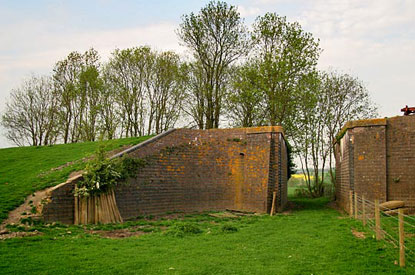
Photo: Four by Three
The next bridge was No.487, built at the southern end of an embankment. It was another example of the engineer’s desire to avoid level crossings and spanned a public footpath which connected Staverton with Lower Catesby. An overbridge soon followed – No.488 – and this stood only a matter of about 3½ chains from the north portal of Catesby Tunnel. Although its lower part was built in blue brindles, the upper section was made of about 4’6” of dressed stone, consisting of eight courses. Why this approach was taken is unknown but was probably at the request of the owner of nearby Catesby House.
The tunnel
The GC had little choice but to build a tunnel here, when a cutting would probably have been feasible. The owner of Catesby House insisted on this, otherwise it would have overlooked the line. His home did have a certain notoriety as it was where the conspirators in the 1605 Gunpower Plot met on occasions, although this has been disputed in recent years.
The tunnel is just short of 3,000 yards long, 27 feet wide and 25’6” high. The whole of the brickwork was faced with brindles which were laid in cement where necessary. It was driven from nine shafts and a small opening in shallow ground. The landowner was unhelpful as a shaft within 500 yards of the northern entrance was not allowed. The first 44 yards were built by ‘cut and cover’, the heading then being driven to meet it. Large volumes of water were diverted into the brick culvert in the six-foot. Five shafts were later lined to ventilate the bore, the most northerly having to be 15 feet in diameter as it was ¾ mile from the entrance. The other four were 10 feet in diameter. The tunnel was straight and built on a gradient of 1:176 which was against southbound trains.
The greatest error in its construction was 1½” out of centre but, in most cases, it was as little as ⅛-¼”. Nearly 290,000 cubic yards of material were removed and about 30 million bricks laid. Construction started on 18th February 1895, with the last length being keyed in on 22nd May 1897. This was claimed as a record in tunnel building. The average rate of work was 110 yards per month, beginning with the first shaft. The best progress was at a rate of 18 feet per day.
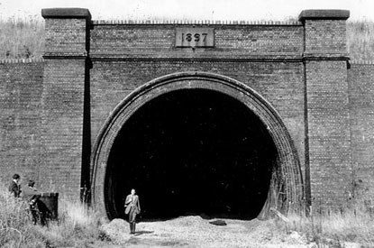
Photo: J Mann
South through Charwelton
The tunnel opened out into a cutting which had contained more than 410,000 cubic yards of earthwork. Near here was the highest point on the London Extension, at 503 feet above datum. At the south end of this cutting, a single span iron bridge carried the Priors Marston to Preston Capes road. This was No.489. Immediately beyond was Charwelton Station which was of the standard country type, the platform being accessed by a road overbridge, No.490. A little further on stood bridge No.491, built for the convenience of the late Lord Knightley who lived at nearby Fawsley Park.
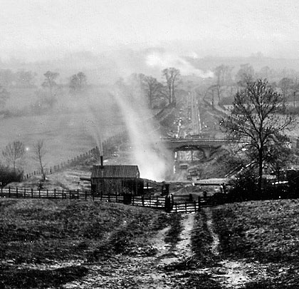
The land was now much more favourable for railway construction and, in late 1903, Charwelton water troughs were completed. They were about ½ mile long and provided the company’s traffic department much greater operating flexibility. Continuing south, the large goods yard, locomotive shed and wagon shops were laid out, with much of this area being created using spoil from the tunnel. The station at Woodford & Hinton was established at the southern end of this complex of tracks. It was another example of the country design but was approached by steps from the road below. As the importance of Woodford increased, the station was completely rebuilt to the form that existed on closure.
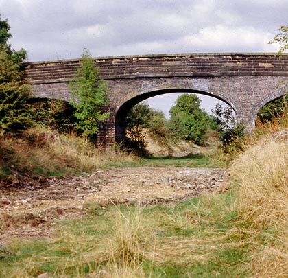
Immediately south was the junction for Byefield and the East & West Junction line. Then came bridge No.498 carrying a minor road. This was another large and very attractive structure. Contract No.4 ended on the north side of the next bridge, No.499, where the East & West passed over the GC.
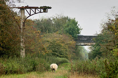
Photo: Four by Three
When the trains had gone
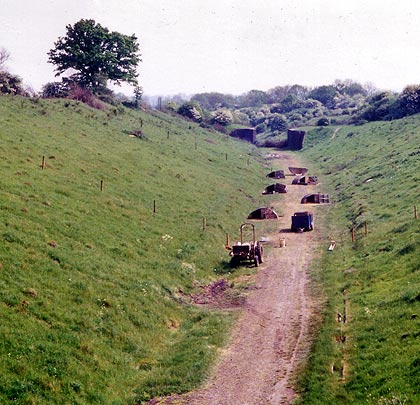
The Great Central main line closed as a through railway on 3rd September 1966, including the section that has been described here. For several years thereafter, it was possible to walk through the tunnel, the southern entrance at least not being fitted with any kind of barrier. However, British Rail eventually added large steel gates at both ends, with smaller gates provided for maintenance purposes.
Apart from this, nature has continually worked to reclaim the land that Thomas Oliver’s navvies tore apart. Indeed it is becoming very difficult to photograph the line’s remains because of this. Many of the structures are extant but notable exceptions are the viaducts at Willoughby and Staverton, and the road bridge which gave passengers access to Charwelton Station. Catesby Viaduct is not in good condition – its fate is uncertain and may not survive much longer without serious maintenance. This of course is highly unlikely.
An unfortunate derailment occurred inside Catesby Tunnel on 4th January 1906. As the 3.25pm Marylebone-Manchester express was running through, the rear vehicles left the rails. The cause of the accident was later determined as a broken rail. Fortunately there were no serious injuries to passengers. The tunnel has recently been considered for further railway use in connection with the London-Birmingham high speed line, promoted as HS2. The idea, now abandoned, was to use the tunnel for one track, with a new tunnel bored for the other.
Click here to download this story as a PDF.
Many thanks to Adam Goodwin of the Record Office for Leicestershire, Leicester & Rutland for his assistance and permission to publish the photographs taken by Mr S W A Newton.
 Dec10
Dec10