


Wilmington's second swing bridge

- Source: Engineering
- Published: 31st January 1908
Wilmington’s second swing bridge
This bridge has been constructed to replace a wrought iron swing bridge, erected by Thomas Cabry in 1853, to carry the Victoria, or East Dock, Railway over the River Hull upon which river is founded the ancient town (now city) of Kingston-upon-Hull. The dock which gave the name to this railway, and which is now known as the Victoria Dock, lies to the east of the river, and north of the ancient citadel, whilst the railway, originally skirting the northern suburbs of the town from east to west, at the present time passes through the thickly populated districts of Sculcoates, Southcoates and Drypool, and forms connection with the subsequently formed railways leading to the seaside resorts of Hornsea and Withernsea.
The railway traffic was very busy and the North Eastern Railway company experienced great difficulty in passing it over the old single-line bridge, particularly as the speed and axle loads were both restricted, although the bridge had been strengthened more than once to meet the more modern requirements. The new bridge is designed for a double-line railway. The Hull Corporation agreed with the railway company to provide, at the Corporation’s cost, a public footway, and this is carried on brackets on the north side of the bridge.
The new bridge was built in close proximity to the old one, notwithstanding that it involved interference with the working of the old bridge, thus necessitating the construction of a temporary foundation on the east bank of the river at a point just clear of the old bridge when opened for river traffic, and of the east abutment of the new bridge. A site, either north or south, which would not interfere with the swinging of the old bridge, would have involved sharp curves in the railway and very great cost by interference with important buildings.
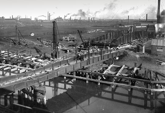
Photo: Mick Nicholson collection
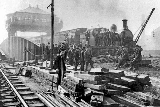
The clear waterway of the old bridge was 37ft 6in, whereas in the new bridge it is 53ft 6in, and provision has also been made under the east, or land, arm for an additional waterway of 40ft in connection with the future widening of the river. The increase in the waterway necessitated a considerable amount of dredging of the river bed, the setting back of the west abutment, and the provision of a substantial river wall about 100 yards long. A clearer idea of what we wish to convey will be gained by reference to the photograph above, which shows the old bridge in the foreground. The far bank of the river is the east bank.
The particular design adopted for the new bridge was largely determined by local conditions. The rail level over the new bridge was fixed by the public road level crossing at the west end of the bridge. It was not possible to raise this level more than 12in, and maintain the road traffic over the crossing. The depth for construction of the steelwork was limited by the height of the water level in the river during floods, the highest recorded flood level being 15.38ft above Ordnance datum, and 4.20ft below the new rail level. By adopting the method of carrying the bridge on a centre pivot a considerable saving in depth was obtained over the usual method of construction of rollers, with an upper and lower roller path.
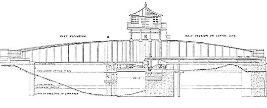
The bridge is built on a skew of 75deg 33min, is 160ft over all, and is 29ft 6in wide centre to centre of main girders. The main girders have plate-webs, and are hog-backed, being 14ft deep at the centre, and 7ft at the ends. The bridge floor consists of rail bearers with cross girders. At the centre of the bridge there are two special cross girders designed to transmit the whole weight of the bridge, by means of a forged steel crosshead and two steel suspension bolts, to the centre pivot upon which the bridge turns. The steel crosshead and the cast iron centre pivot were tested after manufacture with a proof load of 1,000 tons, and the two suspension bolts and the two special cross girders received a proof load of 500 tons each. These proof loads were intended to be 50 per cent in excess of the greatest load to be carried.
The bridge was completed on the temporary foundation, above referred to, on the east bank of the river, and after completion it was intended to balance it there previous to moving it to the permanent position; but owing to a settlement which took place under the temporary centre pier, this could not be done. Its position during erection may be seen in the photograph above, behind the old bridge.
The bridge (including machinery), when completed, was moved into position along a specially constructed path, consisting of a double row of piles with waybeams, and a double line of rails under each main girder. The bridge was carried by eight six-wheeled bogies placed as close to the centre of the bridge as possible, four under each main girder. They were designed to carry a load of 90 tons each. In order that the centre pivot, when travelling with the bridge, should clear the east abutment and top of the roller-path on the centre pier, it was necessary to erect and launch the bridge at a level 3ft 10in higher than it would occupy upon the permanent site.
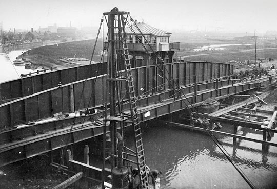
Photo: Mick Nicholson collection
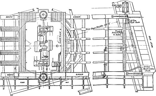
The bridge was hauled into position by a wire cable attached to a locomotive, the power being increased about 12 to 1 by means of blocks etc. The bridge moved freely when travelling. Some delay, however, was caused by two of the rails upon which the bridge was travelling breaking just at the edge of the abutment. These breakages also caused one of the tyres to be sheared off one of the bogies under each main girder. The bridge, when brought into position on the centre pier, was lowered by means of four hydraulic jacks, placed two on each side of the centre pier, under the ends of cross girders 9 and 12, the position of the bridge being finally adjusted by sliding it on greased rails, plates, and rollers by means of jacks placed on the centre pier. The bridge may be seen in position while being hauled in the photograph above; below is the old bridge removed from its foundation.
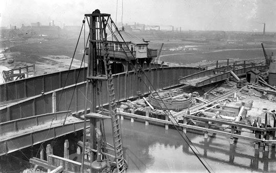
Photo: Mick Nicholson collection
The total weight of steel and ironwork in the bridge is about 460 tons, and the launching weight about 500 tons. The bridge was finally balanced after it was lowered on to its permanent site.
A general description of this bridge having been given, a more detailed account of the turning gear and the way in which the bridge is manipulated will be interesting.
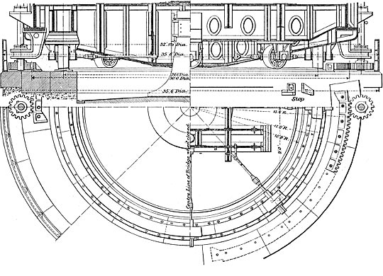
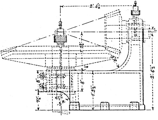
A steel roller path, with eight steadying rollers, is provided. The arrangement of the rollers and centre pivot is shown in the diagram above. If it should be necessary at any time to take the weight of the bridge off the centre pivot in order to renew the bearing discs etc, sufficient rollers have been provided to enable the bridge to be turned as usual, the four centre cross girders being specially designed to take the abnormal loads induced thereby. The centre pivot and rollers are also shown in the photograph below.
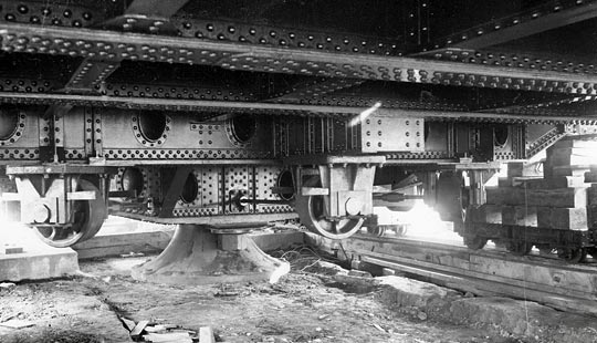
Photo: Mick Nicholson collection
At each end of the bridge, under the bottom flanges of the main girders, wedges sliding into rest plates at the corners of the two abutments are provided to take out the droop of the bridge after swinging, and to fix the bridge in position for railway traffic. These are shown below.
The centre pier, which carries the centre pivot and the roller path, is constructed entirely of 6 to 1 concrete, as are also the two abutments, and the foundations are carried down to the clay which overlies the chalk. This clay is approximately 22ft thick. These foundations are about 19ft below Ordnance datum and approximately 21ft below low-water level. Owing to the proximity of the new bridge to the old one, and also to the nature of the material passed through – this material being silt and warp – great anxiety was caused during the sinking of these foundations, and special precautions were taken by means of trestles, strutting, and tying back the centre pier and abutments of the existing bridge, to prevent settlement or movement as far as possible. It was only possible to use a single-walled cofferdam for the centre pier, and this, composed of 12in by 12in piles tongued and grooved, stood very well.
As the level of the roller path is 12.55ft, and the highest recorded flood level 15.38ft Ordnance datum, it has been necessary to surround the top of the centre pier with a cast iron shield 3ft 6in high, thoroughly caulked and made watertight to keep the spring tides from overflowing into the centre pier.
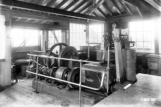
Photo: Mick Nicholson collection
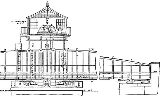
The machinery for inserting and withdrawing the wedges and for turning the bridge is carried in an overhead cabin. An interior view is provided above. The machinery for operating the bridge and withdrawing the wedges by power is in duplicate, and has interchangeable hand-gear for turning the bridge and withdrawing the wedges. The motive power is electricity, supplied by the Hull Corporation. It is conveyed across the river by means of an overhead armoured cable, supported by two steel lattice masts 150ft high, the end of the cable being dropped through the roof of the overhead cabin. The motors, which may be seen in the figures previously referred to, are series wound, and were made by Messrs Siemens Brothers and Co Limited. They are each capable of developing 30 horse-power at 440 volts, and revolve at 240 revolutions per minute.
Each motor is fitted with a double-pole switch and automatic cut-out and fuses, and is controlled by a Siemens’ controller with gridiron resistances. For swinging the bridge, these motors can be worked together, but each motor must be worked by its own controller. The commutator is made of hard-drawn copper, and should stand an inch of wear before it requires to be renewed. The brushes are of carbon, and sparking is guaranteed not to take place until 50 per cent above the estimated load is reached (45 horse-power). The switch-board, which is also fitted for lighting purposes, has the necessary ampere-meter and volt-meter, and was made by Messrs Siemens Brothers. The bracket carrying the bevel-wheel and pinion, which transmit the power down to the circular rack on the top of the foundations, are shown with the wheel and pinion below.
The horse-power required to work the bridge is approximately as follows –
| Starting | Finishing | |
| Withdrawing wedges | 17.7hp | 13.25hp |
| Swinging bridge | 26.5hp | 17.7hp |
| Inserting wedges | 13hp | 14.75hp |
The bridge was opened and closed 30 times at an expenditure of 12½ electrical units. The average time per cycle was two minutes.
In order to facilitate the withdrawal of the wedges by hand when required, by taking the weight of the bridge off the wedges, two hydraulic rams are provided at each end of the bridge. They may be seen in the diagram below. The pump for actuating the rams is in the overhead cabin, and may be seen on the right-hand side of the turning gear. The overhead cabin also contains the necessary levers for working and locking up the bridge. The bridge is in charge of an experienced mechanic, assisted by two steersmen, who divide the duties into three shifts. Three signal boxes control the working of the bridge, two being outpost boxes 345 yards and 455 yards respectively from the centre of the bridge, and the other, the Sculcoates station box, near the west end of the bridge, being for the central control and also for the station and level crossing.
When the bridge is to be opened for river traffic, the bridgeman by bell cable notifies the signalman in Sculcoates station box, who, if no train has been accepted, places his levers, when not already so placed, to the normal position, pulls over a lever to release the bridge, and by a plunging instrument indicates to the bridgeman that the bridge is free for working. The bridgeman will then back-lock the releasing lever in Sculcoates station box, operate the levers which work the latch-bolt of the bridge to disengage the signal rodding, and finally withdraw the wedges and turn the bridge. Special lock and block instruments with plungers are provided at Sculcoates station box, and instruments without plungers at the outpost boxes. The dials of the instruments give the usual indications of the state of the section or trains in both directions, and bells are also provided for indicating the class of train in the usual way. Directly the signalman at either of the outpost boxes replaces the signal for the line leading to the bridge to “Danger”, the signal levers become automatically locked, and cannot again be pulled over until the Sculcoates station signalman plunges his instrument to release the lever electrically. The signals for the lines approaching the bridge at all the three boxes are so electrically controlled by the wedges of the bridge that the signal arms will not fall to the “All right” or “off” position until the wedges are fully home; and if the wedges are partially withdrawn during the time any signal is “off”, the movement will cause the arms to be placed to the “on” or “Danger” position. Telephones connect the three signal boxes, and also connect the overhead cabin with Sculcoates station box.
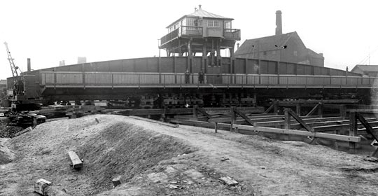
Photo: Mick Nicholson collection
The bridge was designed by Mr J Triffitt, A M Inst C E, assistant engineer, under the superintendence of Mr W J Cudworth, M Inst C E, chief engineer of the southern division of the North Eastern Railway. Mr W McD’Malt was the resident engineer on the work, and Mr H Bruff assisted in the preparation of drawings and in the superintendence of the work. The chief contractors for the work were Mssrs Harman and Langton, of Hull, and the subcontractors for the steelwork Messrs John Butler and Co Limited, Staningley, Leeds, who entrusted the erection to Mr R Woods, of Westminster.
The machinery for turning the bridge and withdrawing the wedges was designed by Mr Wilson Worsdell, M Inst C E, chief mechanical engineer for the North Eastern Railway company, whose contractors were Messrs Cowans and Sheldon, of Carlisle. The signalling and overhead masts were supplied by Messrs Mackenzie and Holland, Worcester.
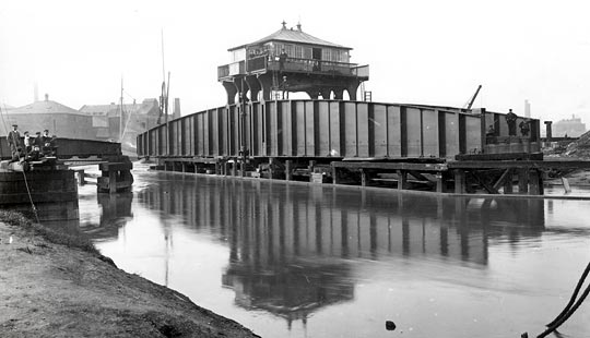
Photo: Mick Nicholson collection
More Information
| British Listed Buildings | Descriptive overview of the structure |
| Forgotten Relics | Gallery of photos showing the bridge |
