Queensbury Tunnel
Queensbury Tunnel


The Act for a railway connecting Halifax with Keighley, promoted by the Great Northern, received Royal Assent in August 1873. Extending northwards from the Halifax & Ovenden Joint line at Holmfield (which the GN had built with the Lancashire & Yorkshire), it would form a triangular junction with the Bradford & Thornton railway at Queensbury, continuing thereafter through Denholme, Wilsden and Cullingworth to an independent terminus close to the Midland station in Keighley.
The local topography imposed many constraints on the three lines radiating from Queensbury. Several tunnels and viaducts were called for, all a product of John Fraser. Born in Linlithgow in 1819, he was a prolific civil engineer, responsible for numerous lines across Yorkshire’s West Riding including sections of the Great Northern’s main line to London. As a result, he went on to be appointed as the company’s engineer. Fraser established a partnership with his son, Henry, in the late 1870s, their subsequent credits including the GN/LNW Joint line from Bottesford to Melton Mowbray. Fraser Snr died at his home in Headingley in September 1881; his son outlived him by just eight years.
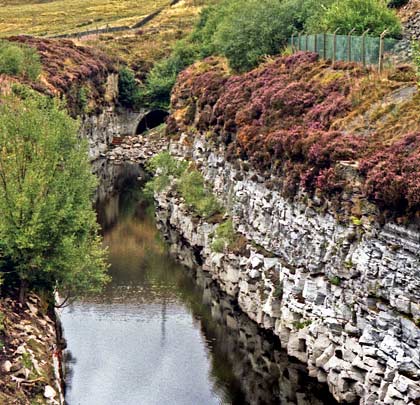
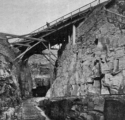
At two miles two furlongs and six chains in length, the Holmfield-Queensbury section – known as Railway No.3 on the plans – would prove disproportionately demanding, and this was reflected in its estimated cost of £179,585. Messrs Benton & Woodiwiss, of Manchester and Derby, were contracted to deliver it. An impressive vertically-sided cutting was excavated at Strines, pushing in an S-shape through the sandstone and millstone grit for 1,033 yards, reaching a depth of 59 feet. This was spanned by a road bridge and aqueduct. At its head was the southern entrance to Queensbury Tunnel which, at 2,501 yards, was the Great Northern’s longest when it first welcomed traffic.
Work on the tunnel had begun on 21st May 1874. Four observatories were erected, from which a view was commanded over each of the construction shafts. Although eight shafts were originally planned, their spacing was subsequently revised and just seven were initially progressed. Shaft No.8 – the northernmost – was the first to be started. The immense influx of water proved a considerable hindrance throughout; the ample pumping provision was almost defeated on several occasions during periods of wet weather. As a result, No.5 and No.6 shafts had to be abandoned when sunk to depths of 266 feet and 196 feet respectively. Of these, the latter was adjacent to Thornton Road, about 2,066 yards from the south portal. Although ultimately to no avail, a driftway – 4 feet square and 120 yards long – was driven out to the hillside from a point 70 feet down the shaft in an attempt to drain the water from it. If finished, it would have been 342 feet deep. But the other shaft was to have been the deepest at 414 feet. This was sited just to the west of New Park Road (then named Kitchen Lane), 1,617 yards from the southern end.
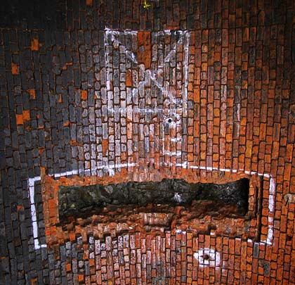
Over the years, rumours have persisted that an additional shaft was sunk, presumably to expediate progress through the northern section of tunnel. If built, there is certainly no sign of it today.Two small apertures in the crown, at around 1,950 yards, have been suggested as its possible location, however consultants working on behalf of the tunnel’s owner, British Railways Board (Residuary), assert that no such shaft was ever constructed.
The remaining five shafts were retained for ventilation purposes. From the south end, these are located at 122 yards (112 feet deep, 9 feet diameter), 399 yards (324 feet deep, 9 feet diameter), 742 yards (379 feet deep, 10 feet 6 inches diameter), 1,165 yards (361 feet deep, 12 feet diameter) and 2,364 yards (125 feet deep, 9 feet diameter).
The shafts passed through coal measures, first encountering the Halifax hard bed (varying from 2 feet to 2 feet 3 inches in thickness) and then the Halifax soft bed (between 1 foot 6 inches and 1 foot 8 inches thick) 20 yards below. The tunnel itself meets one of these beds in the middle and again further north; the predominant strata are sandstone and shale.
A 10-foot square heading made progress from both ends of the tunnel and the bases of the five shafts, making 12 potential faces in total. A three-shift operation was established, with around 20 men per shaft employed on each. At about 3:40am on Tuesday 7th December 1875, six miners returned to their working face after retreating to fire shots, under the impression that all had been successful. They discovered however that one had misfired so Henry Jones and John Gough set about withdrawing it. As they did so it exploded, killing them instantly. Another member of the group, John Rowley, was taken to Halifax Infirmary with head injuries and a broken arm, having been initially tended to by works inspector Mr Albrighton.
On Saturday 10th October 1874, 30-year-old Richard Sutcliffe suffered a fatal compound skull fracture when a rope used to haul a cage up No.1 shaft broke, causing it to freefall to the bottom. Masons Herbert Evans and Thomas Dyson were also struck but survived. In May 1876, miner Richard Jones died when a loose rock collapsed onto him. This pattern of tragedy was repeated during construction of all three routes out of Queensbury, resulting in one newspaper christening them “the slaughtering lines”.
Several types of rock drilling machine were tried in the heading but, whilst a number had proved effective elsewhere, only one was successful here. Major Beaumont of the Royal Engineers – and chairman of the Diamond Rock Boring Company – had developed a machine that was suited to the harder material found at Queensbury. It comprised a frame on which four drills were mounted, with compressed air harnessed as the motive power. In July 1877, it was brought to work from the bottom of No.4 shaft. The rate of progress was three to five times that of manual labour, contributing significantly to the heading’s completion on 2nd October. This event greatly expedited the remainder of the work although, by this time, half the full-sized tunnel had already been excavated and lined.
The following summer brought work to its conclusion and the Great Northern expressed its gratitude by entertaining the 300 men involved to a dinner on 31st July 1878. In late September, a train travelled through the tunnel as part of a preliminary inspection. Major General Hutchinson conducted his examination for the Board of Trade on Wednesday 9th October, deeming railway No.3 unfit for passenger traffic due to the incomplete nature of the works. And so it was a freight only line when the first train enjoyed the 1:100 gradient, descending towards Halifax, on 14th October 1878. Passenger services were eventually introduced in December 1879, after Hutchinson had revisited.
Soon after it opened, significant defects were detected in the sidewalls, partly as a consequence of poor workmanship but also the mining of coal from a seam immediately adjacent to the tunnel. As a result, January 1883 brought the introduction of single line working over the Down (southbound) line, allowing repairs to take place on the west sidewall. The situation was reversed after 12th May and the work was fully completed in September. As it was regarded as a construction fault, Benton & Woodiwiss were required to bear the cost of carrying out the repairs.
In 1890, operators of the local mill, John Foster & Sons, obtained the Great Northern’s permission to extract water from the abandoned No.6 shaft at Sharket Head, although it’s not known whether these rights were ever exercised. A similar arrangement relating to No.5 shaft was agreed in December 1934, resulting in the installation of a pump and equipment to facilitate the shaft’s inspection.
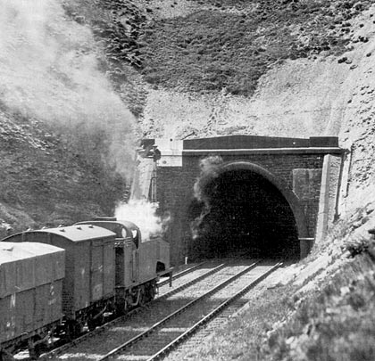
The Home signal for Up (northbound) trains was located just outside the tunnel; the Up Distant was about 400 yards inside it. With locomotives belching out smoke as they laboured up the gradient, the signal proved easy to miss so a mechanical gong – fabricated at the GN’s Doncaster works – was installed 50 yards in rear of it. This was operated by wheel flanges striking a treadle fixed in the four-foot which, in turn, worked a hammer that hit a flat metal plate.
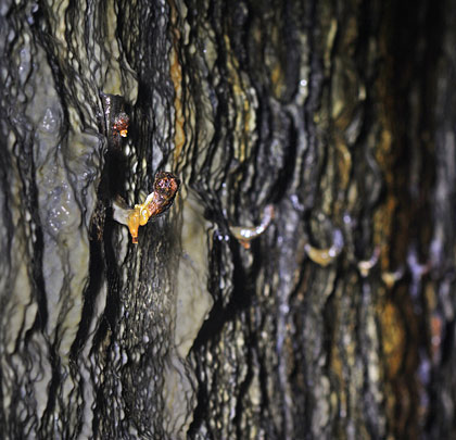
In periods of cold weather, huge icicles could form which would be collected in the tender of the first train through on a morning. These could pose something of a hazard to those on the footplate. Engines were sometimes left in the tunnel overnight, generating heat to prevent their formation.
During 1933, it became apparent that the ground water percolating into No.3 shaft was causing significant deterioration of the brickwork. The Works Committee decided to strengthen and reline it, inviting 13 contractors to tender. Seven responded – although the documentation was incomplete in most cases – with quotes ranging from £2,600-£3,800; proposed timescales were 13-50 weeks. Using materials supplied by the LNER, G A Pillett & Son was engaged to fulfil the project in January 1934, taking seven months and charging £2,637 for their troubles.
The line’s passenger service was withdrawn on 23rd May 1955. Freight continued until the following year, ending on 28th May. Lifting of the tracks took place in 1963.
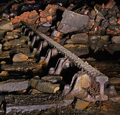
Soon after, a seismological station was established in the tunnel – codenamed QMB – allowing a number of research projects to be developed. In 1973, two Cambridge University scientists, Dr G King and Mr D Young, used an array of strain meters and seismometers to compare the effect of elastic inhomogeneities on surface waves from earthquakes and tidal strains. The recording equipment was housed in a hut which members of the university’s geophysics department sometimes slept in. Access involved driving through the tunnel in a van, dodging the rubble that had been tipped down the shafts when they were capped. The station closed in November 1979 due to safety concerns. The apparatus was resited to Bingley although some metal shelving still survives.
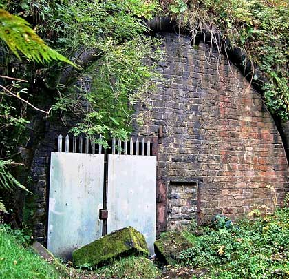
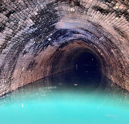
Until recently, the tunnel’s northern entrance had been bricked-up, with maintenance access available through steel-plated gates. This arrangement was replaced with a palisade fence following a programme of repair works in 2012. The southernmost half-mile is flooded, reaching roof level at the portal as a consequence of the falling gradient. This accumulation was prompted by the infilling of Strines cutting and the failure to provide a drainage outlet. However pumps have been used to draw off the water when access is required for maintenance.
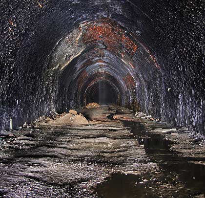
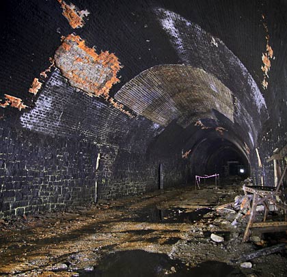
Annual inspections of the tunnel, structure number HQU/3D, had ceased due to the condition of the lining and low levels of oxygen. Limited structural repair work in 2011 allowed inspections to resume, but there remains a considerable amount of bulging or missing brickwork, particularly at the haunches. A major works programme will be undertaken to address the major defects over the next four years.
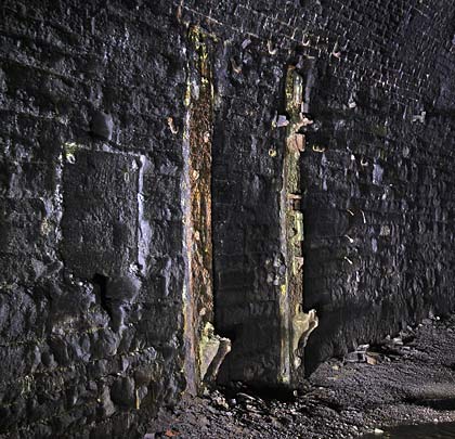
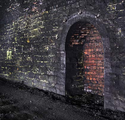
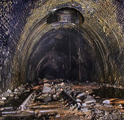
26 feet wide and 21 feet from rail level to the crown, the tunnel comprises vertical masonry sidewalls and a brick arch, although a stone arch is used close to the portals and around some of the shafts. No refuges were initially provided, but six were inserted on the Down side and eight on the Up as part of the 1883 sidewall works. Cable hangers remain in situ, neatly negotiating the refuges; there are also some pulleys for signalling wires.
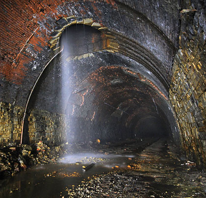
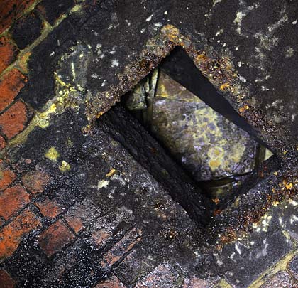
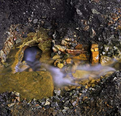
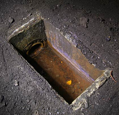
Water ingress, particularly from the northern shaft (No.8), remains considerable. During the tunnel’s operational period, this was managed via a drain located in the six-foot and accessed via catchpits. Several of these remain today but with their lids missing.
The north portal is in a poor state, with open mortar joints and bulging stonework. The parapet was lost in the 1980s and the wing walls have almost gone. This deterioration is ongoing, driven by ground movement, the effects of vegetation and cascading water. Much of the south portal is obscured by a landslip but draining of the floodwater recently revealed it to host an array of telegraph insulator pots and a pair of substantial pattress plates, as well as rounded voussoirs and copings.


