


Civil Engineer G F Adams examines... The construction of Cymmer Tunnel
Civil Engineer G F Adams examines… The construction of Cymmer Tunnel
Although the subject of this paper has been attended by much that is interesting, it would perhaps not have been considered of sufficient importance for a communication to the Institute, from a Civil Engineering point of view only, but coupled with its mining and stratigraphical features it may possess some amount of interest. The tunnel is the principal work in connection with the Llynvi and Ogmore Railway Company’s Northern Extensions, the Act for which was obtained in 1873; the writer’s firm being engineers for the Bill and for the works. It will be observed from the plan that the new lines will form an outlet for new and very important coal fields, and this outlet becomes the more valuable by the amalgamation of the Llynvi with the Great Western system, and by the conversion of the South Wales Railway into narrow gauge.
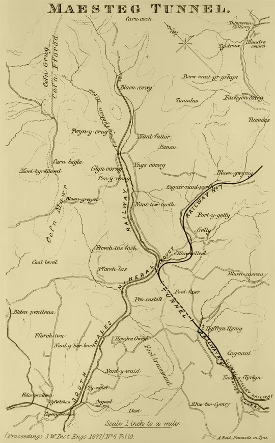
The extensions commence with Railway No.6, which forms a junction with the existing Llynvi Valley Railway near the termination of that railway at Maesteg.
Railway No. 6, immediately after passing through the tunnel, crosses the Avon river by means of a high viaduct, with masonry piers and wrought-iron superstructure. There are four spans of 82 feet 6 inches each, and the main girders are of the “double Warren” type, 10 feet deep, with 10 feet bays. There are cross girders, 10 feet apart, carrying the wooden decking. The height from the bed of the river to rails is 107 feet. The viaduct is built on a curve of 30 chains radius, the rails being level. It was originally intended to build the viaduct with nine masonry arches of 40 feet span, but it was considered that there would be a difficulty in procuring a sufficient number of masons in so isolated a locality.
Near the village of Cymmer a junction with the South Wales Mineral Railway has been effected, and sidings are being prepared for the interchange of traffic.
Railway No.7 commences by a junction with Railway No.6 near the northern end of the tunnel, and runs up the Avon Valley to Blaenavon.
The longitudinal section of the tunnel is compiled from the progress section, supplemented by some detailed sections of the seams taken and supplied by Mr Barrow, and it may throw some little light upon a district which has been the subject of several papers read before this Institute.
The seam of coal passed through at the north entrance of the tunnel would appear to be identical with the seam proved by the Glyncorrwg Company, near Cymmer village, and supposed to be the “Wernddu Seam”, and probably identical with the “Glyncorrwg” or “No. 2 Rhondda” Seam.
The black band passed through near the south end is supposed to be the “Middle Black Band.”
The several faults passed through make it difficult to connect the sections. Very much turns upon the position of the large fault proved in the Llynvi Company’s workings at Cwmdu and Tygwinbach. One would be led to identify it with the disturbance passed through about the middle of the tunnel, by the very broken nature of the ground on the mountain above it, but the rock on each side of this disturbance would appear to indicate that it is not a very large fault in this immediate locality. It may be that the large fault is the one near the south end, in which case the black band ought to have come in again. These are merely suggestions, and it is probable that the ground can only be reconciled by those members who know the district best, and have carried on operations in it, putting their working plans and sections together.
The works were let in two contracts. No.1 contract included Railway No.6 from the north end of the tunnel to the junction with the South Wales Mineral Railway, and the whole of Railway No.7. No.2 contract included the tunnel and Railway No.6 from its commencement to the south end of the tunnel.
The Diamond Rock Boring Company have been the contractors for the section which includes the tunnel.
The tunnel is 1,594 yards in length, and quite straight, with a rising gradient throughout the whole length towards Maesteg of 1 in 226. This gradient is against the load, but it is slight, and could not be obviated, having regard to the levels which had to be adopted near the southern entrance.
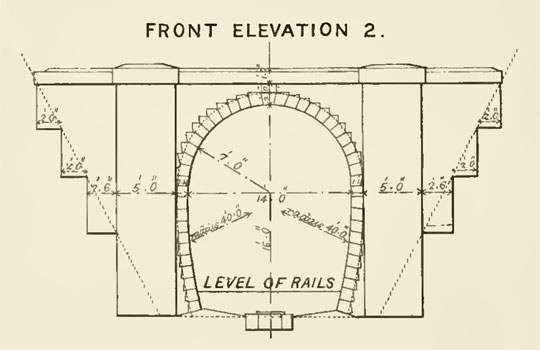
Shown are the contract sections of the tunnel for different kinds of ground. Section No.1 is for soft ground, section No.2 for harder ground, and section No.3 for hard rock. The contracts were for fixed sums, with the exception of the tunnel lining, but it was considered that a contractor, in tendering, would assume, in order to keep himself on the right side, that the most expensive section of lining would be required throughout.
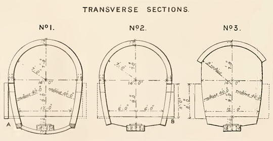
It was therefore decided to get this portion of the work done by schedule of prices, and to change the section as the ground varied, and by so doing a considerable saving has been effected. The following are the contract prices for the different descriptions of work in the tunnel:
| £ | s | d | |
| Excavation in tunnel in every variety of strata and material, per lin. yard | 18 | 10 | 0 |
| Dry masonry in drain throughout bottom of tunnel, per cube yard | 0 | 10 | 0 |
| Masonry set in mortar in invert, side walls, manholes, arching, or entrance of tunnel, per cube yard | 1 | 5 | 0 |
| Brickwork set in mortar in invert, side walls, manholes, or arching of tunnel, per cube yard | 1 | 15 | 0 |
Owing to the inclination and the frequent bedding of the strata, the ground has nowhere been considered quite secure enough to adopt section No.3, although a considerable amount of very hard rock has been driven through, but in order to make the underpinning at the south end easier, the contractors have been allowed to build the side walling vertical over considerable lengths, instead of curving it inwards towards formation level as shown on sections, and this gives a greater width at rail level.
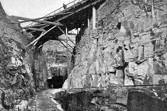
The mountain rising very rapidly at each end, no assistance could be obtained from shafts, and the tunnel has been entirely driven from the two ends.
The south end has been driven entirely by hand labour, and the north end chiefly by machine drills.
The north end was commenced in April 1875, and the south end in August 1875, and a junction perfect to lines and levels was effected on 29th May 1877, 957 yards having been driven from the north end, and 637 yards from the south end.
The following is a description of the machinery which was established for driving the drills at the north end:
The motive power consisted of a pair of portable engines, one 25, and the other 20 horse power, coupled.
The air compressors were a pair of vertical single-acting cylinders, working at a reduced speed from the engine, 30 inches diameter by 2 feet stroke, and going at 35 revolutions per minute; the valves were of the butterfly pattern, self-acting, and 3 inches in diameter; the inlet valves, 19 in number, being placed in the piston, and the outlet valves, 12 in number, being placed in a disc under the top cylinder cover.
Main air-pipes 4 inches in diameter, and made of cast iron. Water pipes 2 inches diameter. Water pressure 90 lbs per square inch; the reservoir being placed sufficiently high to feed the boilers, 10 to 15lbs are sufficient for the purpose of the drills.
In the newer compressors used by the contractors, the piston is solid and the small vacant space at the end of each stroke between the piston and the top cylinder cover is taken up by a little water, which rises and falls with the piston. In this case the whole of the valves are in the top cover, the inlet valves on the outside, and the outlet valves inside the main air channel.
The comparatively slow speed of the compressors enables the heat due to compression to be partially got rid of to the atmosphere, resulting in a proportionate economy of power.
The valves are open to inspection, and, with their seats, can be easily and quickly attended to, but they rarely get out of order.
By having the cylinders single acting, their size is of course doubled, but against this is to be set the absence of slide blocks and guides together with bottom cylinder cover and stuffing box; at the same time the inside of the cylinder and piston is always kept cool by the outside air, and is open to inspection.
The compressors have water jackets, the water entering at bottom, and discharging at top.
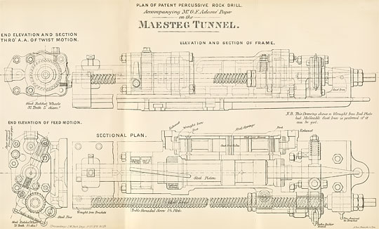
The Beaumont percussive drill has, in common with most drills, three motions, viz – one for giving the blow; one for turning the drill; and one for feeding it forward.
The drill is worked by compressed air at a pressure of from 40 lbs to 50 lbs on the square inch. The apparatus consists of a cylinder carrying a piston and piston rod, which is supported on a frame on which it slides longitudinally, being moved by a feed screw, the feed depending on the speed at which the hole is being deepened.
The drill may look cumbersome, but it is no stronger or heavier than is necessary to do the amount of work which is involved in piercing a 2¼ inch hole in hard rock, at from 2 to 6 inches per minute; in fact, it is work which needs a small steam hammer to do it.
In designing the drill it has been arranged so that all the working parts, which are those only liable to get out of order, are on the outside of the drill.
It is true that they are exposed to the dirt of a tunnel, but that is more than counterbalanced by the great advantage of the miner being able to see, while the drill is at work, that all parts are in proper order.
Inside there are literally only two moving parts, both of which are solid, namely the piston and valve.
One of the chief specialties of the drill consists in the method of driving the valve, which is set in motion by the air in place of, as is usually the case, by some mechanical connection with the piston, or other moving part of the drill. This enables a dead blow to be given in place of a cushioned one.
Where the valve is driven by the piston, it follows that it must be reversed before the drill strikes the rock, otherwise there would be no motion left to shift the valve to the proper position for the return stroke.
By inspecting the drawings it will be seen that each side of the swell in the centre of the valve forming its piston is alternately put in connection with the pressure at either end of the main cylinder, the exhaust being effected through the open space between the two ends of the divided piston of the drill, which is permanently in connection with the outside air, by a hole drilled through the front part of the piston rod.
Suitable buffers are provided for the valve to strike against, and the same arrangement is carried out with the main piston, so that should the piston accidentally overrun its parts no harm will result.
The twist motion is given by two straight and two inclined grooves cut on the front part of the piston rod. They are made both broad and deep so as to afford a proper rubbing surface. When the drill sticks in the hole, as it often does, an excessive strain is thrown on the twist motions of the drill.
The feathers sliding in the latter are in connection with two ratchet wheels, one taking the straight, and the other the twist grooves.
The object of the two descriptions is to prevent the possibility of the drill ever turning back.
The feed is given by putting the brass nut on the feed screw in connection with a pawl driven by a roller which is pressed against the piston rod, prolonged through the top cylinder cover.
The rod is tapered at the end, and as long as the roller keeps clear of the inclined part no feed is given, but so soon as the deepening of the hole enables the piston to move further towards the front end of its stroke the roller descends the incline, and enables the pawl to take a fresh tooth of the ratchet wheel in connection with it.
The drill can be fed, if required, by hand by simply disconnecting the automatic feed arrangement. But hand feeding is discountenanced where speed is an object; indeed, without an automatic feed in hard and variable rocks bad progress would inevitably be made.
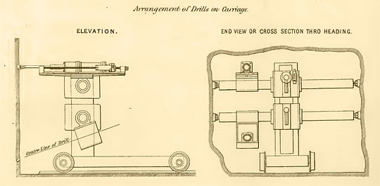
The bed on which the drill slides is of malleable cast iron, allowing a 3 feet length of traverse.
The carriage, or camel as it is called, consists of two arms supported midway by a vertical iron column carried by a low truck running on four flanged wheels. These arms carry two drills each, the top ones being above the arms supporting them, and the lower ones in boxes which hang from the bottom arms.
The object of this arrangement is to keep all the drills relatively in the same position, so that they can be changed one for the other, and so obtain a full command of holding power.
Holes can be put in in any direction, and, as a matter of fact, hand holes are never needed.
It will be seen that the central column is capable of turning; and the arms, again, can turn on it.
The clamps carried by the arms can slide horizontally, and turn upon them, while the drills have similar motions.
When the drilling is completed, the arms carrying the drills are turned longitudinally with the tunnel, and the camel is run back into a siding to allow of the muck wagons being readily passed by it.
For rapid and economical tunnel driving by machinery, it is absolutely essential that a powerful drill should be used, and that the liability to breakage should be reduced to a minimum.
A set of four of the Beaumont drills are capable of putting in 16 to 20 holes 3 feet 6 inches deep in hard rock in three hours, and of keeping this average up.
The advanced heading in which the drills have worked has been driven about formation level in the centre of the tunnel, and 8 feet wide by 8 feet high.
As a general rule 16 to 18 holes are bored into the face, their average length being 3½ feet to 4 feet in hard rock, and 5 feet to 5½ feet in soft ground.
These holes commence with 2⅝ inches drills, and finish at 1½ inches, four to five different drills being ordinarily used in the length in rock, and three inches softer ground. Considerable judgment is required to drill the holes at the angle most effective for the particular ground; as a general rule, the top holes rake upwards, and lower holes downwards.
The boring of all the holes takes about four hours as a general rule.
The four centre holes, converging inwards, are first blasted, then the top and side holes, and after the rubbish has been cleared away in front of them the bottom holes are blasted.
The blasting and clearing of the rubbish takes about four hours.
About 20 lbs of dynamite are used for the above number of holes in rock, and from 10 to 12 lbs in softer ground.
At the above rate a yard is advanced each eight hours, making 3 yards a day, or 18 yards a week.
The average for seven consecutive weeks was 18½ yards per week.
The full complement of men for driving the heading by machinery during one complete operation is, viz – 1 foreman, 1 timekeeper, 1 engine driver, 1 fireman, 1 fitter (outside), 1 fitter’s labourer ditto, 2 blacksmiths, 2 strikers, 2 labourers carrying tools and attending to air pipes, 5 (or sometimes 6) men working machines at face, 5 men blasting and clearing rubbish away, 1 horse driver, 1 miner road-laying after machine and doing any timbering that may be necessary, 1 man attending to explosives/candles etc, 1 boy messenger
26 total
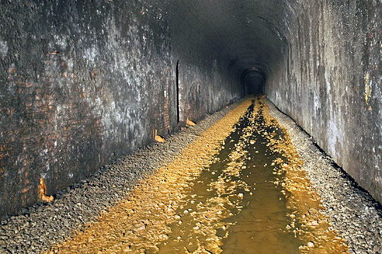
Photo: Richard Knight
The progress of the work has afforded opportunities for comparing results by machine drills with hand labour, and at one time in particular two headings were driven simultaneously in the same hard rock for some distance at the north end, the one by machinery, and the other by hand labour. Over several consecutive weeks the hand labour averaged 3⅓ yards per week, and the machine drilling 18½ yards per week, or five-and-a-half times the speed of hand labour.
Without going into the actual cost – a matter belonging exclusively to the contractors – the writer may be permitted to state, for the information of the Institute, that the actual working cost per yard in hard rock is about the same with machine drills as with hand labour, without taking into account the interest on capital and the depreciation of machinery; in addition to the increased speed, more ground is taken out by the machine drills per yard forward, as headings by hand labour are ordinarily only driven 5 feet by 6 feet; and if the hand heading in hard rock were taken out the same size as the machine headings, the progress in the latter case, instead of being 5½ times greater, would be about 8 times greater. In softer ground the advantage of machine drilling of course decreases; the speed of machine drilling as compared with hand labour would be about as 3 to 1.
The above highly favourable results were not obtained all at once, and are due to the skill and perseverance with which the patentee, Colonel Beaumont, and his agents have displayed in perfecting the mechanical details, and the practical working out of the drill machinery; and before arriving at this successful issue a large expenditure of money had necessarily to be made by the contracting company, in experiments and improvements in the drill, and the appliances attending it from time to time.
For a short time at the early stage of the contract the diamond drill was used, but the cost of the diamonds was found to be too great for this description of work, although the machine remains unequalled for the deep bore holes required in prospecting.
The plant required for driving an advance heading similar to the one at the north end of the Maesteg Tunnel may be assumed to cost about £2,000.
Where only moderate progress is required, and it is wished to incur a smaller outlay, as is frequently the case in mining, a smaller pattern of drill is sold by the Diamond Rock Boring Company with a 3¼-inch cylinder, and 2 feet length of travel; this drill has no automatic feed, and can be worked on an altogether lighter frame than the camel used for large tunnelling operations.
Where the nature of the ground admits of intermediate shafts, and the simultaneous advancement of the different faces thereby gained enables a tunnel to be driven on rapidly, the full-sized tunnel can be more economically driven by keeping the advanced heading on the top, but this system of working affords only one face for the opening out to full size; and where the ground is weak and the face has to be squared down for every length of lining that is put in, the mining during that operation has to come to a full stop. It is therefore necessary, unless time be of no importance, to keep the advanced heading at the bottom, so as to secure several different points for breaking up to full size of tunnel; and it may be stated here that the operation of breaking up was found to be easier going south with the strata rising than in the opposite direction.
At the south end the advanced heading, together with the opening out to full width at the several points, was driven for the most part only to water level. The contractors’ agent who started the work, considering that it would be more economical to go on in this way until the junction afforded free drainage to the north end, and afterwards to underpin the side walls, and bottom up, rather than take the full depth of tunnel down with the gradient, by means of pumps, but time so pressed that pumps had to be applied to assist in these operations before the junction was effected, and inclined roads were driven from the water line to formation level, and from this point the tunnel was excavated to full section forwards for some considerable distance, to the junction with the north end, and the bottoming up and underpinning of masonry, which was done in short lengths, was worked backwards on the rising gradient to the south end. The ground in some places was rather heavy, requiring 14 bars of 15 inches diameter, which is rather heavy timbering for a single tunnel, and in such cases lengths of only 12 feet lining could be put in, the general lengths being 18 feet, four or five centres or ribs being used.
Top headings had, of course, to be driven sufficiently in advance to draw the bars. In some instances where the ground was good several lengths were opened out and turned at a time.
The engineers, having regard to the difference in cost and to the greater durability of stone, elected to adopt masonry rather than brick lining, but the contractors finding the stone, although abundant, costly to dress, and that it took four to five days to turn a length in masonry, whilst it could be done in 24 hours in bricks – an important consideration when the advance heading was at the top, and the ground loose – and having a considerable amount of trouble with the Union masons, applied for permission to adopt brickwork at the same price as masonry. This was granted, and the Pencoed brick adopted.
In turning a length of 18 feet in brickwork, three bricklayers would be engaged, changing from side to side, but in masonry there would be three masons on each side. In brick lining the time in turning a length is taken up as follows – side walls, 10 hours; setting centres, 6 hours; arching, 8 hours
24 hours total.
In masonry lining, two days are taken in building the side walls and two days in setting the centres and arching.
On the 21st April 1876, a very lamentable accident occurred at the north end, in which 13 lives were lost by an explosion of dynamite, in a manhole 176 yards from the tunnel mouth, and where the charges were being prepared. Most of the men were killed in a break-up about 37 yards inside the manhole. The concussion was hardly felt at all in the face of the advanced heading, about 202 yards distant; and some men in a break-up 133 yards from the manhole were also uninjured, but the blast came out towards the entrance with terrific force. The men who were killed were not mutilated, but it is difficult to say whether death was caused by the concussion, or by the very overpowering fumes of exploded dynamite. Probably both causes operated.
The tunnel, which is nearly completed, will cost the Railway Company about £29 15s per yard forward, or about £47,422 for the whole length.
The drills have only been used in the advanced heading, but the writer ventures to think that the time is not far distant when the whole of mining work in driving tunnels through hard ground will be accomplished by machine drilling, especially in cases where the tunnel is taken out full size in one face, although improvements are probably more to be looked for at present in the appliances attending the drills, and in the detailed management of the work, rather than in the drills themselves.
The writer is informed that the same percussive drills are driving a heading in Cornwall 7 feet by 8 feet in the hardest Tin Capel at the rate of 10 yards per week; the progress with hand labour having been only 1 yard per week, the advantages here being ten times in favour of machine drilling, whilst much more ground is taken out – a very important consideration when the heading is driven in the mineral lode.
The Diamond Boring Company have just completed with these drills the junction lengths of bottom heading of the Queensbury Tunnel for the Great Northern Railway Company, near Bradford, and for which Mr Fraser is engineer; the ground was rocky shale and good for progress; an actual rate of 28 yards per week was reached, and during the last month, previous to the heading being holed, a total of 105⅓ yards was driven.
Speed with the advanced heading means actual economy of construction, because an increase in the cost of driving the heading must be set against the cost of the shafts, with all their pumps and gear for working them, which are unnecessary where the bottom heading can be driven sufficiently rapidly.
Take the case of a long tunnel like that at Queensbury, where seven shafts were commenced, five having been put down, and two abandoned owing to the great difficulty of dealing with the quantity of water which was met with. In such a case as this no cost which the use of machinery could put on the advanced heading would nearly come up to the saving effected by the shafts and the pumping being dispensed with. The writer is informed that this tunnel is 2,500 yards long, that the aggregate depth of shafting amounted to 546 yards, and that the quantity of water raised was about 1,000 gallons per minute.
The successful results achieved by machine drilling are likely to give a great impetus to tunnel driving in the future, affording new outlets for our coal and manufactured products; for without machine drilling, or some process of excavating by machinery, the Severn Tunnel, an undertaking of vast importance to South Wales, would probably never have been started, and the Channel Tunnel between France and England, although in softer ground, never seriously contemplated.
