


The Engineer magazine reports on the... Relining of Cwmcerwyn Tunnel
The Engineer magazine reports on the… Relining of Cwmcerwyn Tunnel
An interesting and uncommon piece of work, namely, the reconstruction of a length of 180 feet of the centre portion of the Cwmcerwyn Tunnel, South Wales, on the Port Talbot Railway, without any interference with the traffic on the railway, has recently been carried out by Messrs Perry & Co of Bow.
The Cwmcerwyn Tunnel is about two-thirds of a mile in length, and passes through very mixed and varying strata, such as is common in the neighbourhood, and, consequently, the original mode of construction varied also. In some places, where rock was encountered, the sidewalls were almost entirely dispensed with. The general type of construction, however, consists of a brick-lined roof and sidewalls but no invert; the work is for the most part constructed with four half-brick rings of brickwork in lime mortar. At a few points it was decided, owing to the nature of the ground, to put in concrete inverts for short lengths.
Practically speaking, ever since the opening of the railway, movements have from time to time occurred in the tunnel works in the section of the tunnel mentioned above, which consists of a length of approximately 180 feet, commencing 1,085 feet from the western extremity of the tunnel. Various measures have been taken from time to time to arrest the movement of the sidewalls. In 1898 a length of 35 feet was strengthened by constructing five sections of concrete inverts, and in August 1902, a further length of 70 feet was dealt with in the same manner, with the addition also of heavy timber struts and walings at the toe of the sidewalls. These efforts were, however, only partly successful, as, although the movement in the sidewalls was stopped, the gradual crushing of the arch still continued; and after a careful examination in the early part of 1907, it was decided that steps should be taken to reconstruct a length of the tunnel at the worst point, as it was considered dangerous to leave it any longer.
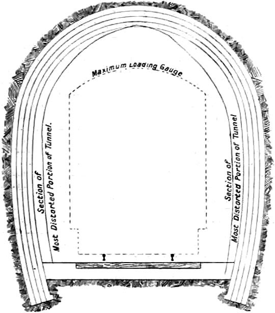
A series of nineteen cross sections were taken in this length by means of a specially constructed gauge on a car, and these cross sections showed that the sidewalls had come in as much as 12 inches in places, and had been distorted outwards nearly 8 inches at others.
In 1907, therefore, tenders were invited from a limited number of contractors for the reconstruction of this portion of the tunnel, either as a brick tunnel, on the same lines as before, or in the form of a cast iron tunnel composed of rings of segments 3 feet wide. The most important work was to be done at times when the traffic was stopped; at the same time the contractors were invited to submit alternative schemes on any different lines which they could recommend, subject, of course, to the approval of the engineer.
Messrs Perry & Co were successful in securing the contract with the specially modified cast iron segment scheme which is hereinafter described. One great point in favour of their scheme was that by it the work could be proceeded with continuously day and night without interference with the traffic. It consisted essentially of the reconstruction of the tunnel with rings of cast iron segments, as suggested by the engineer, but, with segments 20 inches wide and 6 inches deep in lieu of segments 3 feet wide, the traffic on the railway and the men working in the tunnel being protected by a specially designed movable shield or canopy.
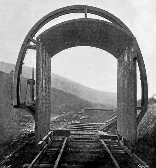
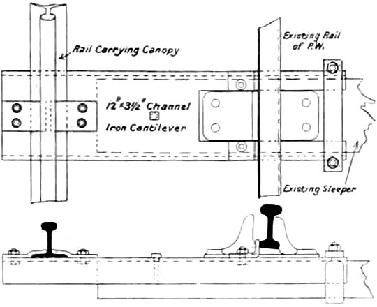
The amount of working space available was, of course, strictly limited, and every inch was valuable. The shield was, therefore, designed, after consultation with Mr Cleaver, the engineer, so as to give a clearance of 4 inches all round the maximum loading gauge. The shield, or “canopy”, is 12 feet in length overall. It is constructed of an angle iron framework and light steel plates. It was, of course, impossible to brace the shield across from side to side, and, as it was imperative that it should be absolutely rigid, it was fitted with a 12 inch stiffening flange or diaphragm at one end. The whole canopy was mounted on six double-flanged travelling wheels running upon rails laid parallel to the existing 4 feet 8½ inch road, supported on specially designed channel iron cantilever brackets which were in turn fixed to the sleepers of the permanent way, and which were connected by means of special clips to the chairs carrying the main rails in such a way that the canopy rails could be adjusted and secured absolutely parallel to, and at a fixed distance from, the main rails. These precautions were necessary owing to the very small clearance obtainable.
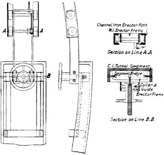
As the working space outside the shield was so restricted, it was considered necessary to provide some mechanical means of handling the heavy cast iron segments forming the tunnel lining, and a form of erector was designed. This consisted of two channel irons which were curved to form a track parallel to the inside face of the iron tunnel lining, and at a distance from it which allowed just sufficient room for a segment to be drawn past those already fixed. The channel iron track was fixed on the leading end of the canopy and securely braced to it, and along the track ran a specially designed erector consisting of a small four-wheeled travelling carriage running between the flanges of the channel track. To the travelling carriage was attached a heavy wrought iron frame carrying a powerful screw, which was operated by a hand wheel and sleeve block. The end of this screw was drilled and tapped to take the set screw which attached the segment bridge to the erector. The “segment bridge” consisted of a heavy wrought iron frame which could be attached to any of the cast iron tunnel segments. The erector was operated by means of a continuous chain running over guide rollers, and a hand grab fixed on a stage which was constructed at one side of the canopy. This stage was at such a height that it would allow a wagon carrying a segment to pass under it.
The method of carrying out the work was as follows. After the last train had passed on Saturday night at about 11:30pm, a length of the permanent way was removed, and the invert excavated for a length equal to that of five rings, or 8 feet 4 inches. Four rolled steel joists were then placed in position, two under each rail of the permanent way, and supported on blockings fixed in the last ring of those already fixed, and upon a portion of the ground ahead. The sleepers and rails of the permanent way were then relaid upon the joists and keyed up. These operations usually occupied the whole of Sunday, the road being relaid in the evening ready for the next morning’s traffic. The following morning the remaining portion of the invert foundation below the iron was put in without interfering with traffic in any way, and the segments forming the invert of five rings, on an average, laid in position and grouted up. The old brickwork of the sidewalls on both sides of the tunnel was then simultaneously attacked, sufficient being cut away to permit one ring to be fixed. These operations were continued on the arch, until the ring was completed and grouted under pressure; the next ring was then erected in the same way.
The amount of brickwork to be cut away varied according as the tunnel was more or less distorted; in some places it was practically nil, whilst in the worst places the whole of the brickwork had to be removed and a portion of the ground behind it also. The rule followed was to grout each ring as it was put in position, so that it should immediately commence to do useful work. For this purpose an air-compressing plant was installed at the tunnel mouth, and pipes laid to convey the compressed air to the grouting machine at the working face. The average speed attained was five rings per week, day and night shifts being worked the whole time. The whole of the brickwork had to be removed by hammers and chisels, or wedges, as blasting was of course out of the question considering the unsafe condition of the tunnel and the amount of traffic passing through.
Very great difficulty was experienced from the smoke and steam from passing trains, although every effort was taken by the railway company to minimise the inconvenience by burning as good coal as was possible, and by issuing instructions to the locomotive men not to fire up in the tunnel. The eastern end of the tunnel for nearly half the length is level, but the grade from there right through the new portion is 1 in 70, falling westwards to the mouth where it changes abruptly to 1 in 40. Consequently it was necessary for all mineral trains to pull up at the top of the grade in the tunnel to permit the brakesman to go along the train and put the brakes all hard on. This naturally occupied some time, during which the locomotive was steaming and smoking, filling the tunnel with fumes which hung for as long as twenty minutes on some occasions, rendering all work absolutely impossible for the time being. After a little time, however, it was arranged with the railway company to put the brakes on outside the tunnel, which materially assisted the progress of the work. Powerful acetylene lamps were used for lighting the works in the tunnel, and were found very satisfactory, but even these were powerless to penetrate the smoke while it lasted, specially during foggy weather.
In order to support the old brickwork of the tunnel as much as possible before cutting it away, the contractors designed some special steel struts composed of steel tube fitted with adjusting screws at one end, which bore upon bearing blocks attached to vertical soldiers or walings composed of rolled steel channel and angle sections riveted together and curved to correspond as near as possible with the contour of the old brickwork, any irregularities in the brickwork being made up with hard packings. The upper strut was fixed just above the maximum loading gauge line, and the lower just beneath the rails and between the sleepers. These struts and walings were used in pairs a few feet in advance of the actual cutting away, and were moved forward one at a time as the work progressed. In the more dangerous places, where the walls were distorted to the greatest extent, additional steel struts were placed in position to secure the walls just above the toe, and with these measures the danger point was safely passed.
.jpg)
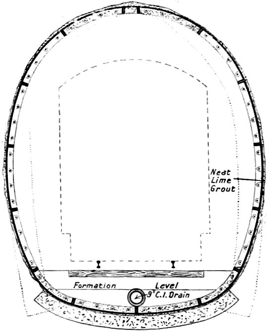
The iron segments forming the inverts were filled with Portland cement concrete level with the flanges, for drainage purposes, and the two crown segments and key were also filled with concrete in order to protect the iron as much as possible from the action of the exhaust fumes. For the purpose of concreting the crown, skeleton steel ribs were made and bolted to the segments to support the temporary sheeting or lagging boards; the concrete was placed in position from the top of the canopy, which formed a good working platform, being provided with angle irons to form footholds.
It is satisfactory to notice that the work was carried out without accident, or delay to any train. The railway company’s chief engineer, Mr William Cleaver, was the engineer for the work.
Published in December 1908
