


Stephen Prior takes a look at the Victorian art of... Tunnel construction
Stephen Prior takes a look at the Victorian art of… Tunnel construction
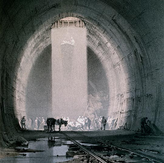
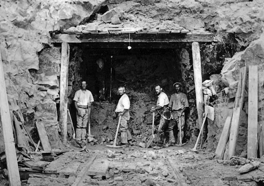
©National Railway Museum/Science & Society Picture Library
There are still over 600 operational tunnels in Britain and more than 500 disused ones. Most were built in the mid-to-late 1800s. Even today visible clues are there to be found showing how they were constructed and what problems, if any, were encountered. Although not officially condoned, next time you explore a disused tunnel remember to take the one item usually never thought of – the humble tape measure. You may discover more than you might think. To understand why, some knowledge of construction methods is required.
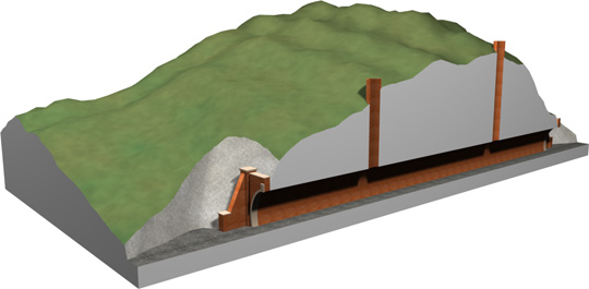
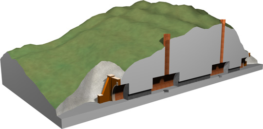
The earliest way to build a tunnel was to start digging from each end and meet somewhere in the middle. Although fine for short tunnels, this method was far too slow for any decent length so another technique involved the use of construction shafts and headings.
This method worked thus: shafts were sunk reasonable distances apart along the alignment of the tunnel. These were usually lined as far as the tunnel’s roof level, then continued downwards to below floor level, supported in timber. By digging down deeper than the floor, it meant that a sump could be formed to collect groundwater.
Once all the required shafts had been constructed, a small tunnel or ‘heading’ – usually in the region of 1.5m high by 1m wide – was driven between the shafts. These were created with timber supports and used to ensure that alignment and levels were correct through the tunnel. In straight bores, candle-pots were often lit at the base of each shaft as a quick way of revealing any discrepancies.
© Record Office for Leicestershire, Leicester and Rutland/’The Last Main Line’
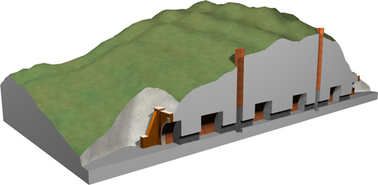
When this stage was completed, excavation of the full bore could be started. So a tunnel with four construction shafts could have a maximum of ten gangs of navvies working simultaneously at ten faces – two gangs per shaft working both ways, and another at each end of the tunnel.
From the base of each shaft, the tunnel was excavated and supported until a ‘side length’ of around 4.5m was formed in each direction. This was built with a lining much thicker than the rest of the tunnel as it had to support the weight of the shaft as well as itself.
Watford Tunnel is one example which highlights the problem with this method. The side lengths were being built when a collapse occurred. This did not only result in the section of tunnel being lost – the shaft was also brought down as it would only have been supported by timbers until this important part of the lining had been completed. Several men lost their lives. What’s not known is whether they were killed outright. Might some have survived the collapse only to die due to asphyxiation? Of course, no-one could attempt any form of rapid rescue as there was no shaft down which they could gain access.
Although navvies were seen as expendable, collapses like this obviously caused a delay in a railway being opened which, in turn, cost the company money. A solution had to be found and a method involving ‘break-ups’ was then employed. This involved more navvies but, being better paid than other manual labourers, they were easy to recruit.
When using this technique, the shafts and headings were constructed in the normal way but work then began on constructing a section of full-sized tunnel anything up to 45m away from the shaft. This was done by the navvies crawling along the heading to a point where this section was to be mined and then opening it up – hence the name ‘break-up’. This may have only been 3m long but had to be solid and very strong as the construction of adjacent sections depended on its ability to support the roof along its entire length. It was now possible for one gang to work towards the next shaft while another worked back to the original one, in the knowledge that they had a safe section of tunnel behind them if anything went wrong.
This method soon became the norm and the introduction of several break-ups between shafts significantly increased production, thus improving the chances of the company making money at an earlier stage. The tunnel at Chipping Sodbury is known to have had 40 gangs working from only seven shafts which would have been impossible had this technique not been adopted.
Tunnelling ‘advances’ – or lengths between break-ups – were normally set at about 4.5m. This was governed by the length and thickness of the timbers put in to support the roof as well as the ability of the miners to move the enormous weight of the timbers forward as they excavated the next length. These main supports spanned from the last length of completed brickwork to supporting timbers at the excavation face. If soft ground was encountered or penetrating water caused material above to become loose, the main support timbers started to take the weight and would bow under the load.
Sometimes, despite making an allowance for this, there was too much bow in the timbers and the brickwork could not be placed to the correct thickness in the roof. This meant that the timbers had to be reset, wasting time and effort. Usually the foreman bricklayer or carpenter paid the men on piecework – so much per yard; it was therefore in no-ones interest to be delayed by having to reset timbers.
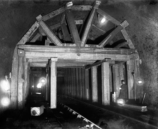
© National Railway Museum/Science & Society Picture Library
At the slightest hint of poor conditions, the foreman bricklayer or carpenter would say how far the next advance had to be in order to be certain of getting the brickwork clearance in the crown of the tunnel. In these circumstances the advance could by reduced to 2m or less so that the timbers did not span so far and were therefore much stiffer, producing less sag under load. That said, advance rates were paramount when paid on piecework and maximum lengths would be resumed as soon as possible.
When two gangs met, a junction length of tunnel was created. It sometimes became a race between gangs to see who could claim the maximum yardage. So if, for example, 7m of tunnelling remained between two sections then one gang may opt to excavate the standard 4.5m thus leaving only 2.5m for the other gang to complete.
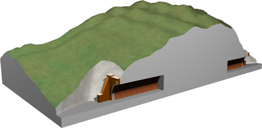
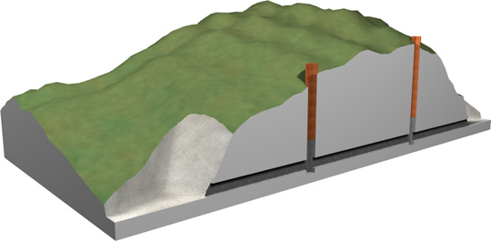
Shaft lengths were created when a construction shaft was not required for ventilation and could be bricked across and sealed. Officially it was backfilled to the surface and the ground above it restored, however abandoned construction shafts have sometimes been found to have been left unfilled, with only a cover at the surface!
Tunnel lengths were always built with ‘dog toothing’ at the ends of the brickwork to form a shear key between lengths. This meant that should a collapse occur then only the section to the next shear key would go, rather than a domino effect causing the total loss of a tunnel. This toothing was not always successful in forming a good joint, resulting in them sometimes being associated with flattened crowns and water ingress. They are very rarely tight and can almost always be seen.
This is where joint mapping can help to reveal things. If it is found that a tunnel generally has the normal 4.5m lengths but they suddenly become shorter, this points towards bad ground, a bricked-up shaft, a junction length or a break-up length. With practice, it should become fairly obvious which has been encountered. Bulging of failed brickwork in a tunnel can be joint mapped either side of the problem which may be found to have been caused by bad ground, a buried shaft or, potentially, a junction length with failed supports. But this method does not work in structures built using the ‘cut and cover’ method or ‘inverted arches’.