


Catesby Tunnel
Catesby Tunnel

Catesby is a colossus, both in terms of length and gauge. Originally planned as a cutting, its existance is due entirely to Henry Arthur Attenborough, owner of the Catesby Estate, who did not want unsightly trains blotting his landscape. Despite his costly stipulation, he was rewarded with the naming of a bridge after him: the first crossing of the railway north of the tunnel is called Attenborough No.1.
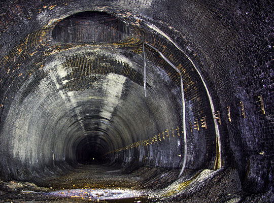
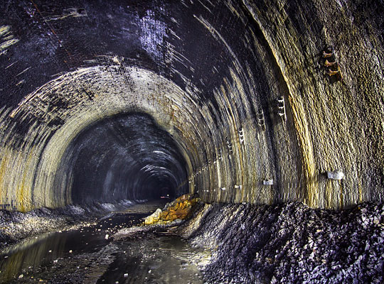
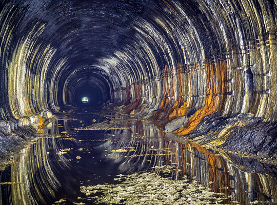
The 2,997-yard structure was cut by Thomas Oliver & Son of Horsham as part of the Great Central’s ‘London Extension’ construction contract No.4. It passes through the upper beds of the lower Lias and the lower beds of the middle Lias. 27 feet wide and 25 feet 6 inches high, Catesby is straight throughout and on a rising gradient of 1:176 to the south, with the summit of this section reached as daylight resumes.
Its creation demanded around 290,000 cubic yards of mining. Work to sink the first shaft began on 18th February 1895 and the last length was keyed in on 22nd May 1897 – a remarkably quick average rate of 110 yards per month. Progress was greatly accelerated by the use of Ruston steam navvies. The first coal trains started running through it on 25th July 1898.
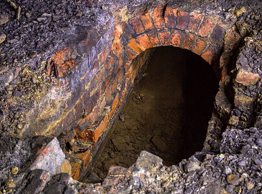
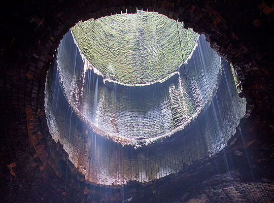
The tunnel was mostly driven from nine construction shafts, each equipped with timber headgear which was used to lower materials to the men working beneath. None though was permitted within 500 yards of the north portal due to Mr Attenborough wanting to maintain the privacy of his residence which stood close to the workings. As a result, 264 yards through very heavy ground had to be constructed by means of a 12x10ft bottom heading and break-ups. This proved liable to breakages and one part completely collapsed. The surrounding strata was under significant pressure which resulted in a heavy lining of seven rings in the arch and sidewalls, with six rings in the invert. These were divided into 10-foot lengths.
Cut-and-cover was used for the first 44 yards from the north portal. The length adjoining this had so little ground cover that the two crown bars were laid from a trench on the surface.
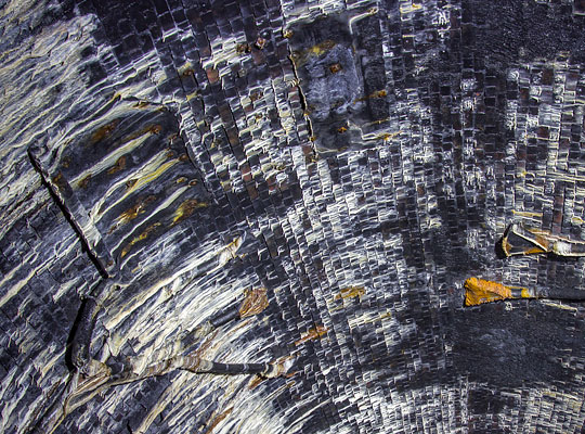
The remainder of the tunnel proved relatively light work and was driven full-sized without headings. Here the lining is mostly five rings thick with a four-ring invert, all faced with Staffordshire brindles and laid in lime mortar. Around 30 million bricks were swallowed up by the structure.
Very little water ingress was experienced, amounting to around 80 gallons per minute. Chases were built into the back of the brickwork at intervals, leading to pipes built through the sidewall at rail level. Water was then discharged into the six-foot drain, accessed via regular catchpits.
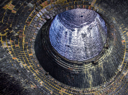
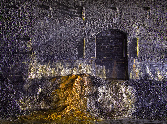
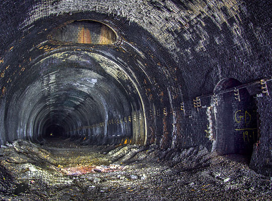
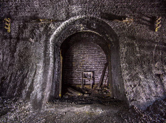
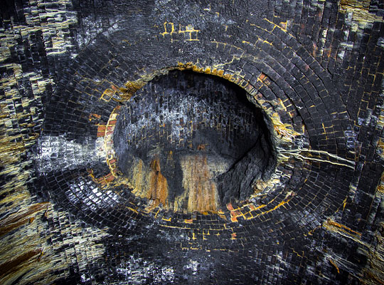
Ventilation is provided by five shafts. Four of these are 10 feet in diameter but the northernmost – 1,250 yards from the entrance – is 15 feet wide to provide greater air flow. The first construction shaft was capped at its base by a brick arch which is still visible; the remaining three – located about 780, 1,010 and 1,435 yards from the north end – are now hidden behind the lining.
Both lines through the tunnel were inspected by the local ganger twice daily. In the winter of 1906, this role was carried out by Joseph Turner, as it had been for the previous 18 months. At about 4:20pm on 4th January he completed an examination of the Down line. Half-an-hour later, a London-Manchester express with upwards of 50 passengers on board entered the south end of the tunnel at around 60mph. As it approached the fifth shaft, a rail broke beneath the locomotive and all five coaches behind it derailed, ripping up 450 yards of track. The last carriage became detached and came to a stand foul of the adjacent Up line as a goods train was approaching. Only prompt action by the driver, who put down a detonator, and the guard, who sounded the whistle, prevented a collision.
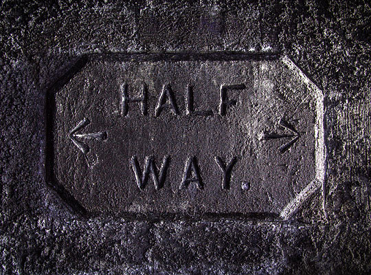
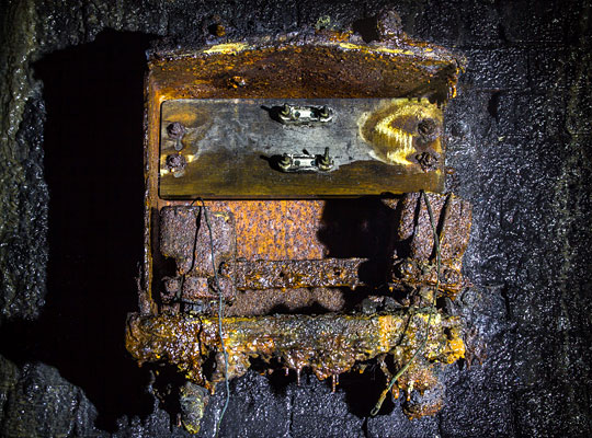
Trackworkers were relatively well served with refuges provided on both sides and three rest cabins cut into the Up sidewall. One is located directly opposite the tablet that marks the “half way” point.
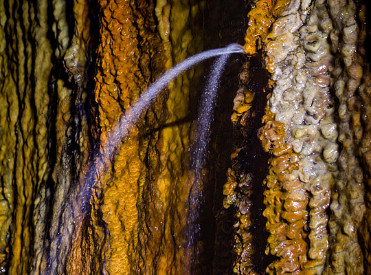
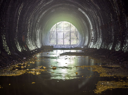
Catesby Tunnel retired from operational service on 3rd September 1966 since which time the permanent way has been removed. Water ingress compounded by a blocked drain just north of No.1 shaft means that, in places, it is flooded to a depth of a foot or more. Calcite makes it presence felt with some significant formations.
Over recent years, the structure has featured in a number of reopening plans. In 1997, Chiltern Railways’ Evergreen project proposed a link from Aylesbury to a parkway station near the M1/M6 junction and then onwards to Leicester. This would have passed through the tunnel. The Central Railway (CR) freight scheme sought to link Liverpool and Lille via the Great Central’s former alignment. But a review of the proposal carried out for affected local authorities found that “Catesby Tunnel does not correspond remotely to the loading gauge to which CR aspire.”
And HS2, the company set up by the government to consider possible routes for a north-south high speed line, looked at an alignment (Route 4) which could have used the existing tunnel for one line of a two-track railway or over-bored it to a width of 11 metres to accommodate both lines. In the end, the preferred route followed a course several miles further west.
In the autumn of 2014, proposals emerged to convert the tunnel into an aerodynamic test facility for road and race cars. These were subject to planning approval which was granted in February 2017.
Click here for a gallery of exterior and archive pictures.
Thanks to Tony Sabey for the information on Mr Attenborough.

 June 2017