On this day in 1892, 134 years ago, the first ground was broken for the Lancashire Derbyshire and East Coast Railway under the stewardship of resident engineer Cecil Brown.
Featured videos...
Join us socially...
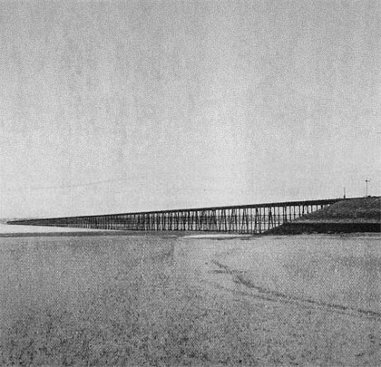
Solway Viaduct
Solway Viaduct
1/9
<>
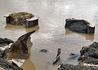
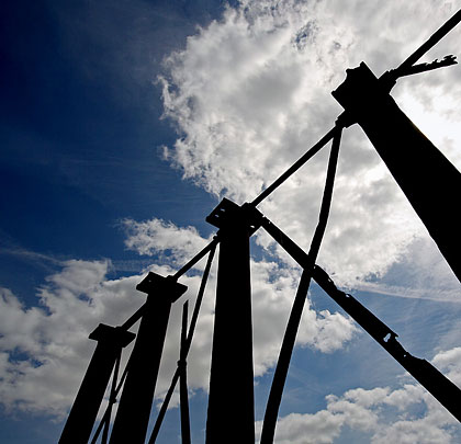
At the end of the southern embankment, one and a half piers remain.
<>
An astounding feat of engineering, the 5,790-foot viaduct across the Solway Firth was a product of designer Sir James Brunlees, working for the Solway Junction Railway. It took three years and around £100,000 to erect. The deck – in either 30ft or 40ft plate girder sections – was supported on 181 piers, most of which comprised five braced iron columns. In total, 1,224 piles had to be driven. These were each 12 inches in diameter and mostly installed from pontoons.
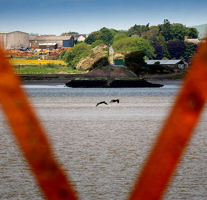
At the English end, a 440-yard approach embankment was built; a shorter earthwork carried trains the remaining 154 yards onto Scottish soil. Both were protected by revetments. Between them, the track was carried 34 feet above the water.
The first freight train crossed Solway Viaduct on 13th September 1869 but it was almost another year before a passenger service was introduced. In 1875, 33 of the columns had drainage holes cut into them, allowing water to escape rather than freeze inside them. Six years later, ice flows partly destroyed the structure. Following three years of repairs to 43 damaged piers, the viaduct continued to serve the railway until falling into disuse in 1921. Salvage crews arrived to demolish it in 1934, much to the annoyance of some folk on the Scottish side who used it to cross into England where alcohol was available on Sundays.
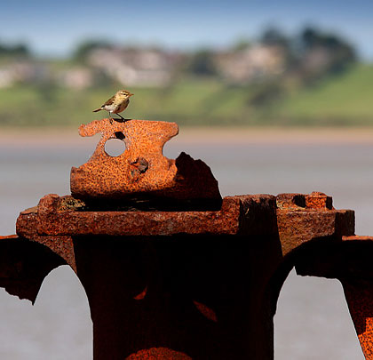
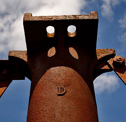
Today only the southernmost pier remains, marooned at the end of its deteriorating embankment.
November 2009
Solway Viaduct
Pwll-y-Pant Viaduct
1/8
<>
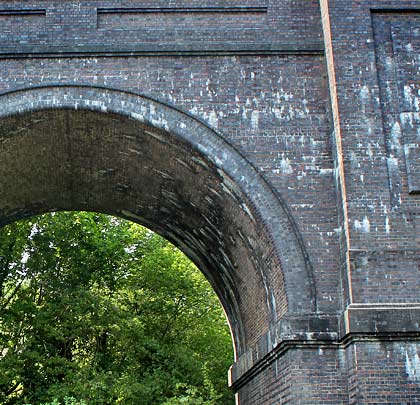
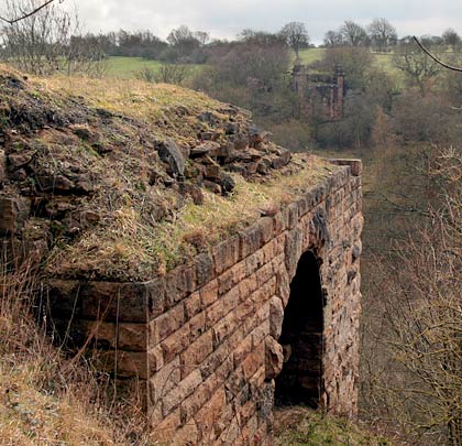
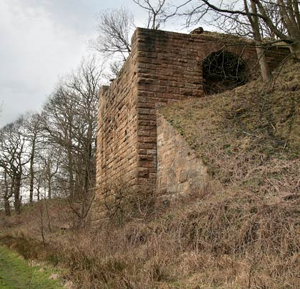
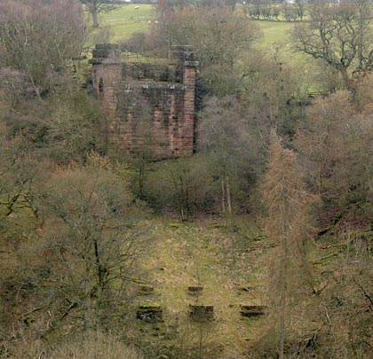
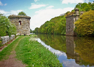
All that remains of Pwll-y-Pant Viaduct is a single 36-foot brick arch at its western end, flanked by king piers.
<>
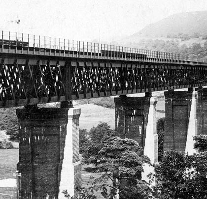
Authorised by an Act of 1898, the Brecon & Merthyr extension of the Barry Railway extended for 4½ miles to the coalfields on the eastern side of Rhymney Valley, cutting nine miles off the existing circuitous route. Trains first travelled over it on 2nd January 1905.
The principal engineering work was a double-track viaduct of 800 yards at Pwll-y-Pant, crossing the main line of the Rhymney Railway and the river of that name. Responsible for the engineering were Sir John Wolfe Barry and Cuthbert A Brereton, whilst Alexander Dickie acted as Resident Engineer.
Comprising the structure were 11 steel lattice girder spans, each 170 feet 11 inches in length, resting on brick abutments and ten piers, eight of which reached over 100 feet in height. At its north end were four semicircular brick arches of 36 feet; a single brick span was provided at the south end together with an adjoining bridge over the Rhymney Railway.
Excavations for the northern abutment were started in October 1902. As with the southern abutment and piers 1, 8, 9 and 10, the foundations were carried down until rock was encountered at depths varying from 10-24 feet. Piers 2 to 7 were founded on hard gravel, 11-20 feet below ground level. The piers, abutments and arches – representing upwards of 18,000 cubic yards of brickwork – were fashioned in a little over 15 months.
The northern section, where the first girders were erected, was on a curve of 20 chains radius. In order to launch the steelwork, timber trestles of 22-66 feet in height were established in line with the straight portion of the viaduct. From these, the girders of spans 10 and 11 – forming the curve – were jacked over into their permanent positions whilst span 9 was carried forward.
Each lattice girder featured 275 tons of steelwork, resting on fixed rocker bearings at one end and 8-inch deep cast steel rollers at the other. They were 17 feet deep and placed 16 feet 3 inches apart. All the web members were formed of channel bars to avoid any undue straining when the girders were suspended at their centres during the construction process. The first consignment of steelwork arrived on 25th September 1903; span 1 was the last to be positioned on 7th October 1904.
The deck consisted of 1-inch wrought iron plates, sitting on cross girders – 27 feet in length – which projected over the main girders to provide room for pathways on each side of the viaduct. Beneath the deck was a gangway for inspection and repainting purposes.
By the middle of November 1904, the entire structure was complete. 29th December brought the Board of Trade inspection, each span being loaded with six 72-ton locomotives, three on each line. These were run across at various speeds and the deflections recorded, amounting to 1¼ inches at the centres of the girders.
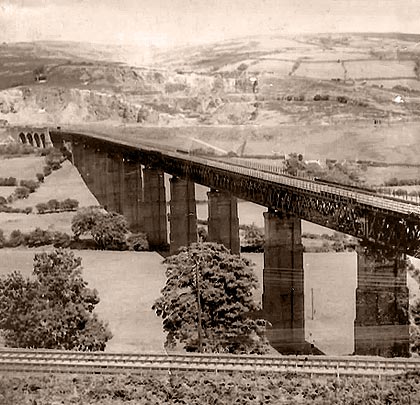
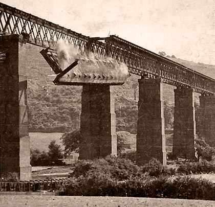
Innovation and enterprise might have engineered the viaduct but it did not bring commercial success for the route over it. Just 21 years after its inauguration, an Act of Abandonment brought the curtain down on 4th August 1926. The structure sat idle for more than a decade – still gracing its landscape – but was sold for scrap in 1937, yielding its buyer 3,377 tons of steelwork. The dismantling process came to an end the following year with the blowing up of the piers. (See our ‘Railway films‘ page for two clips of the demolition on the British Pathé website.)
Today only the single brick arch at the south end remains, together with the adjacent king piers. These stand in the garden of a house on Central Street, with a footpath passing beneath the span.
November 2009
Pwll-y-Pant Viaduct
Knowsthorpe swing bridge
1/9
<>
At both sides, the bridge was approached on substantial embankments built from eight local pit heaps.
In 1893, a number of engineering firms in Hunslet, Leeds, obtained an Act of Incorporation for the Hunslet Railway Company, with the aim of establishing local facilities for the handling of their goods, dissatisfied with those afforded by the Great Northern Railway at Wellington Street, two miles away. The GN saw several benefits in this scheme and, a year later, took the company over.
Plans for the line were prepared by W B Myers-Beswick – a regular servant of the Great Northern – whilst the works were contracted to J T Firbank of London. The main line was 3¼ miles in length, but the vast goods yards near South Accommodation Road pushed this distance to four miles.
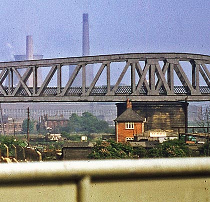
Much of the track was laid on embankments, material for which was brought from eight pit heaps, some as far as three miles away. But the principal engineering feat was a six-span bridge over the Aire & Calder Navigation and adjacent River Aire at Knowsthorpe (or Knostrop). As a concession to the waterway’s authorities, it was agreed that the span over the Navigation should be constructed in such a way that a swing mechanism could subsequently be installed, thus accommodating plans for the possible formation of a ship canal into Leeds.
The resulting structure was vast: a clear span of 170 feet across the waterway and 275 feet between abutments. The two main girders, 41 feet apart, extended for 295 feet, with a depth of 30 feet. The weight of their steelwork amounted to 1,250 tons. The ashlar column supporting the main span was 45 feet in diameter whilst the foundations for the piers were sunk to a depth of 35 feet. To test the span’s strength prior to the line’s opening, the free end was jacked up, the support rollers and bed plates removed, then the deflection was recorded as the jacks were gently lowered. To counterbalance the forces exerted on the long arm when loaded, a weight of 157 tons had to be applied to the short arm. This was achieved by boxing in its main and cross girders, thereafter filling them with cast iron.
Work on the structure got underway in January 1897, under the auspices of Darlington’s Cleveland Bridge & Engineering Company, the appointed subcontractor. Three men lost their lives during its assembly and two others sustained injuries.
Immediately beyond the main span were two short steel-deck sections over a narrow ribbon of land separating the Navigation and river. The latter was crossed by a pair of bowstring girder spans supported by a pier standing in the water. The track over the bridge ascended on a gradient of 1:100 to the south, with the structure incorporating a curve of 25 chains in radius.
Leeds’ ship canal never came to fruition and the main span was never adapted to swing. The line over it closed on 3rd January 1966, although the section from Beeston Junction to Middleton Colliery exchange sidings was retained until 3rd July 1967. At the north end, Neville Hill-Hunslet East Goods officially remains open but very rarely sees traffic.
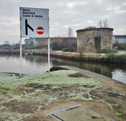
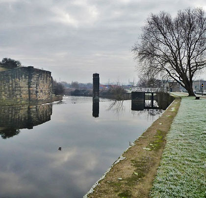
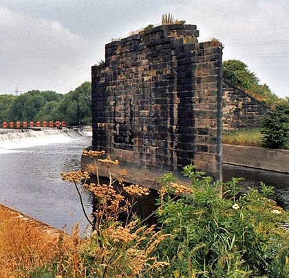
Ogden Demolition dismantled the bridge in 1977, leaving only the masonry column for the swing span, the northern abutment and the mid-river pier.
(Christine Johnstone and Dr Neil Clifton’s photos, taken from Geograph, are used under this Creative Commons licence.)
August 2012
Knowsthorpe swing bridge
Deepdale Viaduct
1/8
<>
A distant view of the western abutment from the east side.
This cast and wrought iron viaduct, opened in 1861, was designed by Thomas Bouch as part of the South Durham and Lancashire Union Railway.
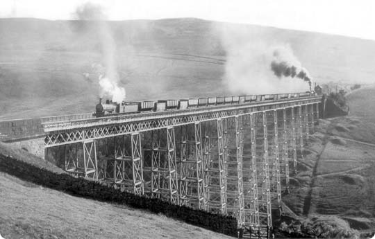
Consisting of 11 spans totalling 740 feet, the structure crossed Deepdale beck at a height of 161 feet. Closure of the line came in 1962 and the viaduct was dismantled a year later – a process captured by a foresighted, local photographer.
April 2013
Deepdale Viaduct
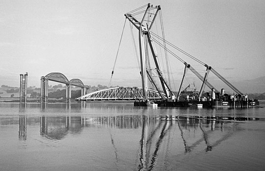
The story of the Severn Railway Bridge: Lost in the fog
For business or for pleasure, through need or curiosity, daily life generally entails some form of travel. Anyone employed by the railway can be thankful of that fact. Rarely though do journeys live long in the memory – your eventual destination being the real draw. But what if you never get there? What if fate intervenes? Fifty years ago this month, George Thompson and James Dew set out on separate journeys that would have appalling consequences for five of their colleagues and one bystander – a piece of spectacular railway engineering.
Frenzied development
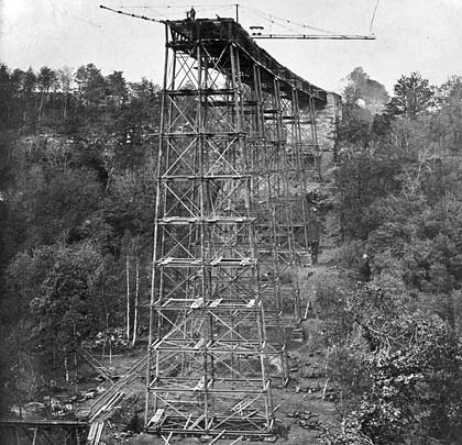
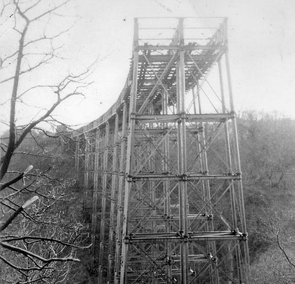
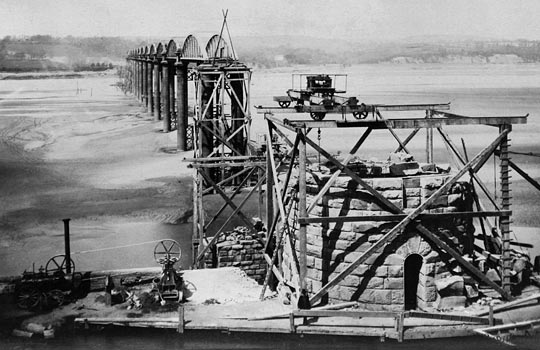
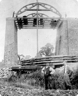
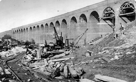
Taken on 27th January 1877, this shot shows the construction of piers 12, 13 & 14 and is from a fabulous album of construction photographs held at and reproduced courtesy of the Gloucestershire Archives (Ref B417/23554).
Today, those robbed of daylight as their train plunges beneath the river between Severn Tunnel Junction and Pilning probably don’t think twice about the engineering of that four-mile black hole. Neither will they care that it was not the first attempt to link the Severn’s west and east sides with a tunnel. Work to extend the Bullo Pill Railway through to Arlingham had reached the river’s midpoint when, on Friday 13th November 1812, an inrush of water flooded the excavation, leading to its abandonment. All lives were thankfully spared.
But the network’s development through much of the 19th century, coupled with the financial rewards to be reaped from South Wales’ colossal coal reserves, were to spawn an abundance of similar visions. None was more audacious than Brunel’s 1844 proposal for north and south-facing bridges – each around 800 yards in length – forming part of plans for a line linking London with South Wales, crossing the water eight miles south-west of Gloucester. The city’s businessmen, alive to the commercial impact of being bypassed, mounted a vigorous and ultimately victorious campaign against it, securing the route still in use today.
The drawing board remained busy with six proposals emerging in 1871 alone. Included within this collection were the Severn Tunnel Railway and the Severn Bridge Railway No.2. The former navigated its parliamentary passage in August 1872, welcoming a trial goods train on 9th January 1886. At its peak, 3,628 men laboured on it. The latter would also come to fruition but those who paid for it probably wished it hadn’t.
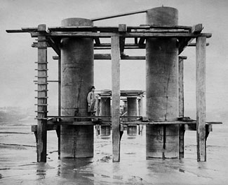
The pier cylinders and temporary staging pictured on 24th March 1876. Photo: Gloucestershire Archives (Ref B417/23554)
Conflicting interests
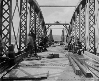
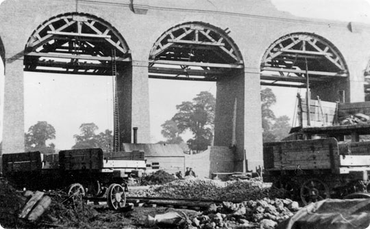
On 16th June 1876, a group of workers take a break during the construction of spans 2 & 3. Photo: Gloucestershire Archives (Ref B417/23554)
Engineered by George William Keeling and George Wells Owen, the four-mile Severn Bridge Railway formed a junction with the Severn & Wye and South Wales railways at Lydney, then disappeared into a tunnel of 506 yards before climbing onto the bridge to cross the water. At the east side, it joined a branch of the Midland Railway at Sharpness Docks.
Powers were taken to raise its £278,000 estimated price tag. The Severn Tunnel, which had also been granted Royal Assent, was likely to cost three times as much. Although the distances between London and South Wales via the two routes were comparable, the bridge benefited from gentler gradients; this lulled the company’s directors into believing that they would secure the lion’s share of that lucrative coal traffic.
Running powers over the route had been granted to both the Midland and Great Western railways – they could exercise these through investments of £50,000 in the project. But their conflicting interests brought much delay, eventually demanding mediation. When decision-makers found against it, the initially-supportive GWR walked away to focus its attention on the tunnel.
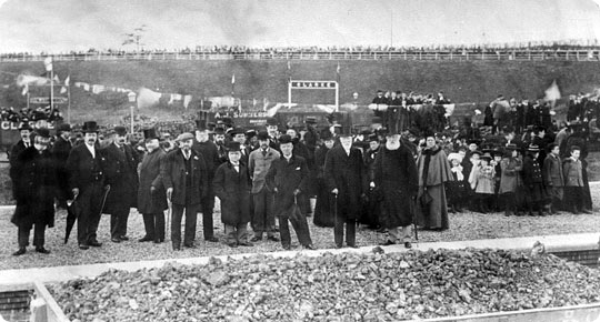
Bickering and financial navel-gazing gave way to physical progress on 3rd July 1875 as company chairman W C Lucy laid the two-tonne foundation stone. Hamilton’s Windsor Iron Works Co was awarded the £190,000 contract to erect the bridge whilst Vickers & Cooke – later to be replaced by Griffith Griffiths – was tasked with delivering the remaining structures and stations, work valued at £90,000.
Assembly in situ
On 8th May 1877, work on the masonry support for the swing bridge is making good progress. Photo: Gloucestershire Archives (Ref B417/23554)
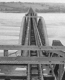
This was a venture of enormous scale and complexity, made all the more formidable by the Severn’s great tidal flows. 4,162 feet in length, the bridge consisted of two spans of 327 feet over the main channel, with 19 lesser spans and a swing bridge at its eastern end across the Gloucester & Berkeley Canal. The western approach was carried on a 13-arch masonry viaduct – no mean feat in itself.
The pier columns were formed of 4-foot cylindrical sections, 10 feet in diameter. The first dozen piers had to be sunk through 28 feet of sand before bedrock was found. Extensive staging was assembled from which the cylinders were lowered on chains bolted to the inside flanges. Felt-lined to deal with expansion, they were then filled with concrete. A primitive piling machine helped to drive the sections through a clay ridge close to the east bank.
A 10-knot tide rising 30 feet in a little over two hours precluded on-shore construction of individual spans prior to them being floated into position. Instead the staging was extended upwards to allow assembly of the ironwork in situ. This operation attained such efficiency that many of the spans were erected in a week, with bolts used as a temporary fix before the riveters came along to provide a permanent one.
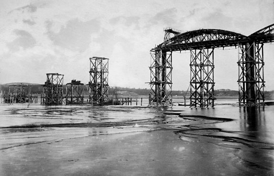
The greatest challenge – that posed by the navigation channel – faced engineers in the autumn of 1878. Initial efforts were thwarted by the tide which washed away the staging and several pier cylinders; massive timber piles were snapped at their base. But the following February brought the first span’s completion. Work on the second benefited from floodlighting, making the introduction of a night shift possible, and reached its conclusion in August. Eight locomotives took part in rolling load tests, deflecting these spans by just 1½ inches. Their construction did though claim the life of workman Thomas Roberts who plunged into the river from deck level, a distance of 70 feet, striking the staging on his way down.
Crowds gathered at every vantage point to witness the first public train rumble over the structure on 17th October 1879. On its return run, a detonator was exploded on each of the 21 spans. After crossing again, passengers got off to accompany W C Lucy onto the bridge where he ceremonially tightened the last bolt. What would the HSE have said? It was an act of great symbolism, not least because 24 hours earlier The Great Spring had penetrated the Severn Tunnel’s top heading, flooding the workings to river level. No progress was made there for over a year.
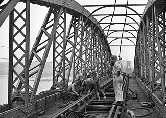
Brace yourself
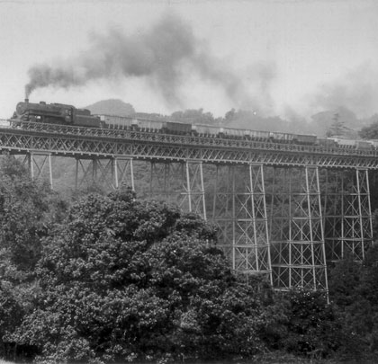
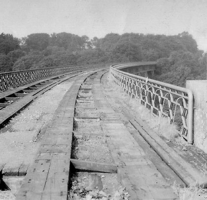
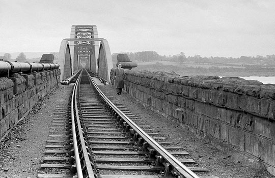
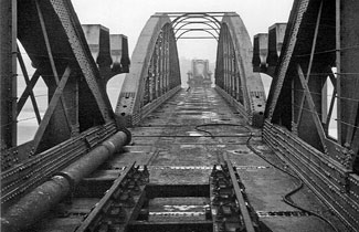
A view along the bridge from the west side of the river. Photo: Brian Hillier
But any sense of smugness was shortlived. Expected traffic levels failed to materialise and the company’s financial resources were drained further by the Severn & Wye Railway – a servant of the Forest of Dean’s ailing coal industry – with which it had amalgamated in 1878. Losses were cut in 1894 when, with most trains heading for the now-open tunnel, the company was transferred to the Midland and Great Western, under the control of a joint committee. The bridge was effectively bankrupt.
In 1955, a detailed examination prepared the way for heavier locomotives to use the structure, providing an alternative route from South Wales to Bristol. The following year, with strain gauges installed to record the deflections, a series of tests was carried out involving two Castle-class locomotives, eight loaded Grampus wagons and a brake van. The outcome was a £125,000 contract let to Fairfields for the strengthening of almost 500 diagonal braces.
Work got underway in 1960, with the firm afforded a nightly possession of the bridge after the last train had passed over at 2145. By late-October, three spans were complete and scaffolding encased a fourth. But suspect ironwork was soon to be the least of the bridge’s problems.
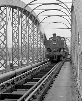
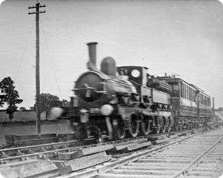
On 19th October 1956, ex GWR 0-6-0PT 1639 crosses the bridge. Photo: Brian HillierThe view looking west from the signal box on the swing bridge. Photo: Brian Hillier
Power of the tide
Calm greeted James Dew, skipper of the Wastdale H, as he eased his vessel out of Avonmouth Docks at around 1915 on the evening of Tuesday 25th October 1960, embarking on the return leg of a journey that had begun in Worcester early that same morning. Travelling with him was a crew of three and 351 tonnes of petroleum spirit. Slightly ahead, he could see the lights of tanker barges which had sailed up from Swansea on the afternoon tide. Amongst them was the Arkendale H, loaded with 296 tonnes of Britoleum fuel oil and captained by George Thompson.
Although visibility was good, the area around Berkeley Power Station – three miles downstream of the bridge – was notorious for thick fog, a function of cool air blowing over the sun-warmed foreshore. And so it was that evening – by 2200, 16 craft were enveloped.
As he passed the power station, Thompson swung his barge around to stem the tide, punching into it at such a rate as to overcome its power. As he reached the piers at Sharpness marking the entrance to its docks, a tug towing several barges crossed his bows, forcing him to kill the power and drift upstream. As he lined up for a second attempt, the Wastdale H emerged from the murk on his port side. On board, Dew was fighting the tide and his ignorance – this was only his third day on the river.
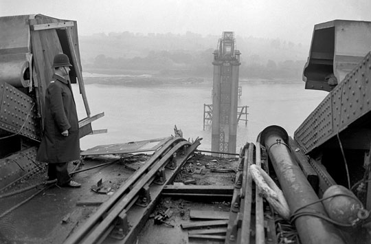
As they came together and unknown to either skipper, a crewman on the bow secured a line between the vessels. They were now inseparable. Thompson and Dew battled to prise their craft apart but succeeded only in losing control of them. Caught by the fast-flowing current, they were pushed upstream towards the bridge. Travelling sideways, the Wastdale H slammed into Pier 17, turning the vessel over. The Arkendale H ended up on top of her. As Thompson emerged from his wheelhouse, the pier and the two spans it supported fell onto the stricken craft.
A police officer surveys the damage the morning after the night before. Photo: Press Association
Mounting the rescue
Supervisor T C Francis left the signal box at Severn Bridge Station, on the western bank, at 2230. As he walked down onto the bridge, a sheet of flame burst skyward; an explosion followed. He ran back to the box to call the emergency services. On his return, he was confronted by a hole where once there were girders. Still burning fiercely and burdened by the collapsed spans, the barges were carried upstream before grounding on a sandbank.
Thompson had been struck by flying debris and lost consciousness for a time. Once revived, he found his mate Percy Simmonds and engineer Jack Cooper on the stern. Knowing that neither could swim, he gave each of them a life belt and instructed them to jump. He did, they didn’t. With the river ablaze all around him, Thompson had no choice but to swim for survival.
Dew too was in the water. He clambered on board the Arkendale H where he found the two men wondering what to do next. They had already inflated a life raft but it drifted away. Dew led them onto the deck from where they walked into the water. Cooper was swept to the stern of the vessel and caught by its still-revolving propeller. He was eventually rescued. Remarkably, Dew was found uninjured three hours later, upstream of the bridge. The tide carried Thompson for three miles before depositing him on the bank.
The remaining crewmen – Simmonds (34), Jack Dudfield (46), Alex Bullock (40), Robert Niblett (25) and Malcolm Hart (17) – all succumbed.
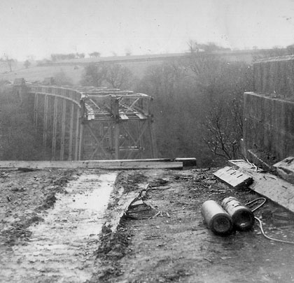
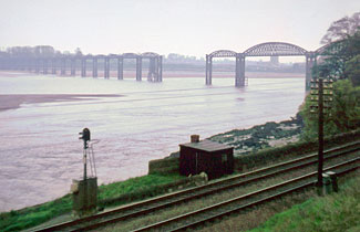
The collision resulted in the loss of Pier 17 and the two deck sections supported by it. Photo: D J Norton A view of the damaged bridge from Purton on the river’s west bank. Photo: John Thorn
Accident prone
The fate of the bridge was engulfed by protracted debate. Rebuilding costs were estimated at £312,000 against £250,000 to dismantle it. Local opinion favoured the former as the structure provided an important community link, particularly as the children of Sharpness took the train to and from their school at Lydney on the opposite side.
In December 1961, an underwater survey discovered extensive damage to Pier 16 which was leaning towards the east bank. A contract was awarded to erect a temporary trestle, eliminating any danger of collapse. Days before work started, an upturned tanker drifted into Pier 20 on the ebbing tide, causing a further £13,000 worth of damage. This same pier was again the victim when the contractor’s twin-hulled crane broke from its moorings; the deck’s underside was also struck by its jib. The bill on that occasion was £6,000.
By 1965, British Rail wanted only to cut its losses, having received just £5,000 in compensation for the original disaster. Twenty-four companies were invited to tender for the demolition work; 20 withdrew their bids following a site visit. Nordman Construction – not one of the remaining four – got the job.
Demolition of the bridge involved a floating crane, the Magnus II. Photo: Press Association
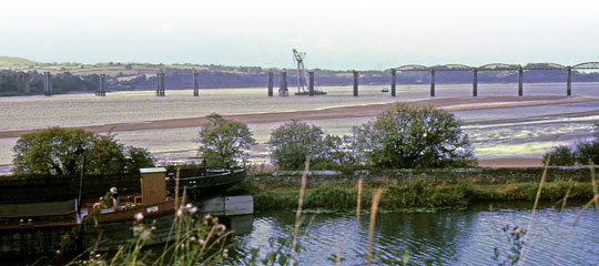
On Tuesday 22nd August 1967, a huge floating crane, Magnus II, was piloted up the Severn. With a propeller at each corner for maximum manoeuvrability, it boasted a lifting capacity of 400 tonnes to a height of 150 feet. When she left three weeks later, the swing bridge, three spans and 21 piers were still standing. It was not until 10th March 1968 – three months after the deadline – that another company, Swinnerton & Miller, finished the job with explosives. It was another two years before the debris was cleared.
A group of workers assist in the bridge’s dismantling. Photo: Press Association Debris from the demolition littered the Severn until 1970. Photo: Peter Coleman/ TammyLynn Photography
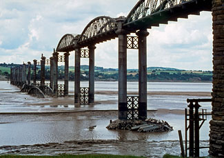
Mighty bridges
Whether to go under, over or around was the conundrum posed by Britain’s great rivers when the railway reached their banks in the 19th century. In meeting nature’s challenge, engineers crafted mighty bridges. Whilst the Forth, Tay, Royal Border and Royal Albert continue to shine, the Severn’s lost crossing stands alongside them, if obscured by the mists of time.
Viewed from above the Gloucester & Berkeley Canal, the Magnus II worked its way along the bridge, removing the deck sections. Photo: Graham EdgeworthRemaining ironwork from one of the western piers tries hard to keep its head above water. Photo: Midland Explorer Boy The central support for the swing bridge also survives, together with some of the masonry approach viaduct at the eastern end. Photo: Midland Explorer Boy
The story of the Severn Railway Bridge: Lost in the fog
The story of Gree Viaduct’s demolition: Last Arch Standing
With the ravages of middle age securing an ever firmer hold, my part-financing of the National Health Service through 24 years worth of income tax payments looks an increasingly sound investment. That and my shares in Ralgex. It can only be a matter of time before some creaking body part completely gives up the ghost. The exterior finish already looks suspect.
Of course, society’s obligation to nurse and restore tired, crumbling relics only extends to human kind. Even listed buildings cannot always claim immunity from prudent financial stewardship. Witness the recent demise of Giffenmill Viaduct and its near-neighbour Gree, which grandly straddled Lugton Water – about 15 miles southwest of Glasgow – for over a century. The sense of melancholy is palpable with the benefit of rose-tinted spectacles.
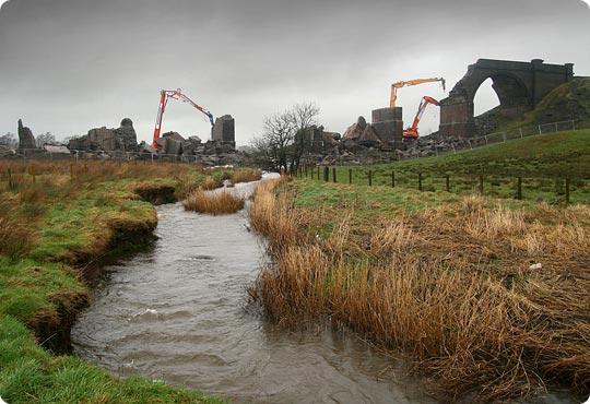
Viewed from the south, Gree’s last arch loses its battle for survival.
Like its more famous, surviving relative at Glenfinnan, Gree helped to sharpen the cutting edge of structural technology, hence its Grade B listing. Both were offspring of locally-born engineer Robert McAlpine who earned the nickname of ‘Concrete Bob’ for his pioneering use of the material. The inaugural train tested Gree’s muscle in 1903, the same year that the world’s first reinforced concrete high rise broke the skyline in Cincinnati. But the 16-storey Ingalls Building was already a generation ahead of Ayrshire’s humble viaduct.
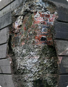
Cast concrete rings formed each of the 11 arches. A cement render, fixed with timber pegs and mimicking the appearance of traditional masonry, softened its impact on the local vista. But the mass aggregate infill – built-up in layers and comprising ample 300mm stone – lacked any of the steel reinforcement we’re familiar with today. This was a structure under huge tension and, contrary to the belief of its builders, was not resistant to the ravages of snow and rainfall.
Since its redundancy notice was served in the Fifties, a section of parapet wall had given way; refuges threatened to part company. Water had penetrated the carefully crafted façade causing spalling and movement through freeze-thaw. An ugly truth was revealed as the render fell – Gree was an accident waiting to happen. Sooner or later, claimed consultants Ove Arup and Partners, it would succumb to the inevitable and collapse.
This iconic monument served only a cosmetic purpose – no future function was realistically envisaged. Refurbishment would have proven costly – in excess of £1.2million – and problematic, given uncertainties over the precise make-up and strength of the structure. But when its owners, British Railways Board (Residuary), set the wrecking ball of demolition rolling in 2002, objectors’ heads soon rose above the parapet. Emotion clashed with logic, though the latter eventually won.
One of the piers shows typical damage.
Gree’s first step towards destruction had actually been taken in May 1995 with the granting of listed building consent for the lion’s share of the structure, sitting to the west of Lugton Water. Administrative boundaries float above this watercourse, cutting the viaduct through its eighth arch. The project went nowhere as rail privatisation stole everyone’s attention.
Seven years on, BRB(R) lodged new planning applications with councils on either side of the water. A comparatively easy course was navigated through North Ayrshire’s processes but five more calendars had been torn from the wall before East Ayrshire reluctantly put its thumbs up. Legal agreements were prepared to secure passage for a possible footpath and negotiations concluded with landowners.
It was Christmas 2007 before Raynesway Construction – celebrating the award of another framework contract for the Board’s projects in Scotland and northern England – finally gained access to site. A compound was soon established which connected with the A736 via a 350 metre haul road. The burn was then spanned by a temporary bridge – providing access to the three eastern arches – as well as a crash deck fashioned from sheet piles, sleepers and timber supported on stone-filled bags. Plans to install a culvert were overruled by the Scottish Environmental Protection Agency which voiced concerns over its possible impact on breeding salmon. Assessments even took into account the possible presence of pearl mussels. There weren’t any.
With an exclusion zone established, Burnfield Demolition moved in with specialist excavators – one standard and two long-reach machines. BRB(R) policy demands that only companies approved by the National Federation of Demolition Contractors can raze its unwanted estate.
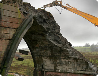
A long-reach hydraulic breaker beats the last arch into submission.
The north-side parapets were first to go. Then slices of deck and arch were chopped away along the structure’s length, narrowing it in stages. This gradually reduced the load, ensuring that residual forces would continue to be transferred from arch into pier. Cutting through a complete arch would have created the climate for an uncontrolled, progressive collapse, akin to the domino effect. Only when a 1.5 metre wide section remained was an arch finally knocked through.
The structure withstood this onslaught remarkably well, defying gravity on occasions. Nonetheless, when I visited site a fortnight after battle had commenced, just a solitary arch was still standing. In biblical rain and the wildest of gales, I watched hydraulic breakers beat it into submission. It was a surreal scene reminiscent of a disaster movie. I was half expecting Burt Lancaster to enter stage left, clawing through the wreckage for survivors. A handful of men, armed with the mechanical advantages of the 21st Century, reduced 9,000 cubic metres of concrete and a little piece of history to rubble in five weeks.
Fittingly, Gree is once again part of our transport infrastructure. Its considerable fabric was crushed, processed and stockpiled on site before relocating to East Kilbride where, today, it supports a roundabout. Its original home was green again in July. The access bridge and crash deck are gone; fences and drainage have been reinstated. Where recently there was only mud (much of it, as I discovered, slightly deeper than the average welly), graded top soil and grass seed now lie.
Despite adding much to Ayrshire’s landscape, the condition of Gree Viaduct had become a cause for concern.
Ayrshire’s countryside has a new feature – a 211 metre window of fresh air, framed by two embankments. Given time, the many locals who bemoan Gree’s passing will see the natural beauty beyond. One of them paid a final pilgrimage to the viaduct shortly before it came down. His online recollections describe “a noisy gaggle of geese numbering over a hundred, flying from the south and circling back over this crowning landmark as if to salute this colossus of the steam railway age, and perhaps say a fond farewell to an old friend.”
The story of Gree Viaduct's demolition: Last Arch Standing
Author: Graeme Bickerdike
Source: Rail Engineer magazine
Published: May 08
The story of Brackley Viaduct by John Quick: A modern railway by any standards
The pleasant market town of Brackley lies in the south-west corner of Northamptonshire, very close to the counties of Buckingham and Oxford. It is an ancient borough and was of considerable importance in medieval times. Indeed, it was at Brackley where the Barons met King John before the signing of the Magna Carta. Its long, unusually wide main thoroughfare is lined with attractive stone buildings and the area is well-known for hunting, with the Grafton and Bicester kennels nearby.
The railway age arrived at the town on 1st May 1850. The Banbury to Verney Junction line of the Buckinghamshire Railway was a single track cross-country branch with a station serving Brackley at the bottom of the town. Naturally enough, when the Manchester, Sheffield and Lincolnshire Railway – later to become the Great Central – opened its station, it was known as the top station. The news of the MSLR’s intention to build a new railway through Brackley and on to London created much debate and excitement. It became evident that the MSLR planned to build a locomotive shed and workshops. The opposition to this was considerable and was lead by the Squire of Turweston, John Locke Stratton. He was also Mayor and a major landowner. The MSL eventually decided to construct their engine depot at Woodford, about 10 miles to the north. With a population of well over 2,000, Brackley would have been a useful source of labour for the company.
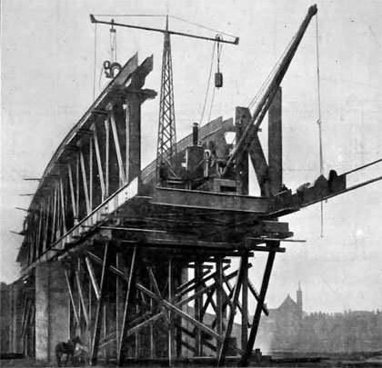
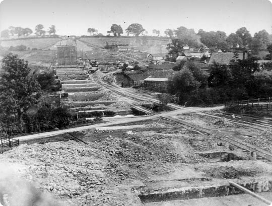
In the summer of 1895, the foundations of Brackley Viaduct take shape. Photo: GCRS/John Quick collection
Royal assent to the MSLR’s bill to build the line – often termed the ‘London extension’ – was received in late March 1893. Tenders were issued for the construction of 92 miles of main line which commenced at Annesley North Junction, about 9 miles north of Nottingham, thence to Quainton Road in Buckinghamshire. At that point, trains were able to use the Metropolitan Railway into London.
The construction of the London extension was split into northern and southern divisions, the dividing point being the viaduct over the Oxford Canal near Rugby, 51 miles 69 chains from Annesley. The engineers for the southern section were Sir Douglas and Mr Francis Fox, and it consisted of contracts 4, 5, 6 and 7. The line in the immediate vicinity of Brackley fell entirely within contract No.5. This was 12 miles 39 chains in length, began just south of Woodford and terminated nearly half-a-mile south of the bridge which crossed the Banbury-Verney Junction line – this was structure No.532.
On 7th September 1894, the engineers recommended that contracts 5 and 6 should be let together. This was because there was little suitable ballast on contract No.6 but more than sufficient on No.5. Topham, Jones & Railton of Westminster put in the lowest tender but that company had already secured contract No.3. As a consequence, J T Firbank was nominated for contracts 5 and 6. However, on 21st September, the MSLR board gave contract No.7 to J T Firbank, then instructed William Pollitt, General Manager of the MSLR, to offer contracts 5 and 6 to Walter Scott & Co of Newcastle. This was accepted at a reduced tender of £470,000. Other contractors who failed to get any work were Kirk, Knight & Son of Sleafard, Monk & Newell of Bootle and S Pearson & Son of Westminster. The first brickwork on number 5 contract was laid in November 1894 when work started on a small 6’ culvert, a few hundred yards north of the passenger station site.
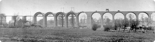
The viaduct’s western elevation in the spring of 1896. Photo: GCRS/John Quick collection
Looking at the engineering features on contract 5, we begin at the northern end, a little more than a mile north of the station. Crossing a cutting at Brackley Fields was built a brick arch bridge, No.524. It was 31’0″ high with a square span of 56’6″. It carried a farmer’s track and, in common with the vast majority of similar structures on the line, was built in Staffordshire blue brindle bricks. The line continued in cutting until it passed beneath the road to Towcester. The official plan of the line shows three possible sites for this bridge. The central site was selected and became bridge No.525. It consisted of three arches, the outer two being made wide enough to accept additional tracks which, unfortunately, were never needed. Structure 525 was about 25′ high and over 100′ long. It was demolished some years ago in an attempt to straighten the road which, by this time, was carrying a lot of traffic.
The passenger station was situated immediately south of bridge 525. This station has been described as ‘typical London extension’ but this is not really correct. In truth, it is unique on this line. The MSLR was hoping to use the bridge for public access to the platform but the local authority was unhappy at the proposal as they considered the arrangement would interfere with road traffic! Perhaps the Squire was busy again? The MSLR then had little choice but to build its booking and other offices at the top of the embankment on the Down side. A footbridge connected the public entrance with the platform. The station master’s house stood on the Up side, more or less opposite the booking office.
Wagons laden with wooden-arch formers sit in front of Brackley’s southernmost arch which was later replaced with a steel girder span. Photo: GCRS/John Quick collection
The platform buildings were identical to those at Rugby. In fact, all the buildings on the line between Whetstone and Calvert were executed by a Rugby firm, J Parnell & Son, for about £30,000. The platform was the usual island type but there is evidence that a third platform was considered. Opposite the Down side were the earthworks for this and, on an official plan, the words ‘future platform’ are noted alongside. It has been referred to as the ‘Northampton platform’ but this is generally thought to be a myth. The earthworks were extant when the line closed in 1966. The goods yard contained all the necessary features to deal with a variety of traffic.
Passing the station, the line continued on its slight curve to the south-east on embankment. A small underbridge, No.526, pierced this, giving the farmer at Burwell Farm access to fields on both sides of the line. It stood nearly 19’ high with a span of 12′. Then came the valley of the River Ouse. Standing more or less at the 147½ mile post was built Brackley Viaduct, one of the major works on the London extension. With the corn mill standing alongside, construction probably began in the winter of 1894/5. It was intended to build 22 arches but this was not the outcome. Locals warned the contractor of unstable ground in the district and, despite the placing of large quantities of wool in the foundations, serious problems were encountered. The viaduct was largely complete when cracks were noticed in the southernmost two arches. Photographs show these and also damage to a nearby store. Urgent remedial action was required and this consisted of the removal of the offending arches and replacement with two steel girder spans, with a massive reinforcement of the next pier. Viaduct No.527 was over 750′ long and a little over 60′ high. It was demolished with great difficulty during the autumn of 1978 – against locals’ wishes – apparently for the hardcore. Immediately south of the corn mill, the contractor had their local head office, with workshops, stables and accommodation for 200 men.
Making good progress – the parapet wall is added above three arches in the summer of 1896. Photo: GCRS/John Quick collection
The main road to Buckingham was carried over the line, about ¼ mile to the south, by bridge No.528 which stood close by the county boundary. It had one arch only, was 17’ high and had a skew span of 33′. The cuttings on the approach to this bridge have now been filled. South of this point, the railway crossed the main valley of the Ouse on a high embankment which contained over 270,000 cubic yards of rubble. The nature of the clay here was already understood from the days of the construction of the Verney Junction line. Consequently few problems were found in this area. The line of that railway was crossed on an overbridge, No.532, with a skew span of 51′ and a 26′ square span. It consisted of four plate girders, 58′ long. A temporary siding was laid to assist with the considerable traffic in construction materials. Ten chains to the south, contract 5 ended with a small under bridge. This was structure No.533 and crossed a footpath which connected the villages of Evenley and Westbury.
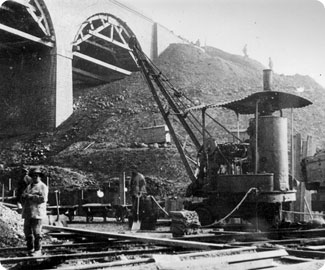
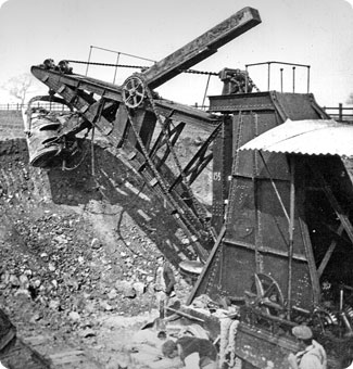
The early days of railway building depended a lot upon men wielding the tools of their trade. These were mainly hand tools – pick, shovel, wheelbarrow. Horses were used as well. But the construction of the London extension was a vastly different affair. Small, four or six wheeled steam locomotives worked over the lightly-laid tracks of the contractor, moving materials and spoil. The steam excavator – or ‘steam navvy’ – was used with great success. They were supplied by Ruston, Proctor & Co of Lincoln and, on an average day, could move about 250 loads, equivalent to about 1,000 cubic yards.
Construction of the London extension benefitted from steam-powered machinery. Photo: GCRS/John Quick collection A steam navvy at work near the Buckingham road bridge. Photo: GCRS/John Quick collection
They revolutionised the removal of material, saving both time and money. It has been estimated that one excavator was the equal of perhaps 70 men and the cost of removing one cubic yard of material could, depending on the nature of it, fall by anything between 25% and 45%.
When the first main line railways were built, the activities of the makers were recorded by artists such as J C Bourne, but this was not the case with the London extension. The construction of this line was comprehensively photographed by a young, very enthusiastic Leicester photographer, S W A Newton. Newton took very many photographs during the line’s construction, showing the men, their plant and many more subjects. Something in the order of 3,000 photographs and negatives exist and a great many have been published. The Newton Collection is available for study at the Leicestershire Record Office. It is a unique record of the construction of what has been called ‘the last main line’.
The viaduct nears completion in the summer of 1896 only for cracks then to appear in the southern two arches (right). Photo: GCRS/John Quick collection
The MSLR became the Great Central Railway whilst the line through Brackley was being built, only a change of name was required. On 15th March 1899, the first passenger trains called at Brackley although the line had been in use for coal traffic from July of the previous year. The GCR became part of the LNER in 1923 and, in turn, that company was absorbed into British Railways in 1948. The London Midland Region of BR took responsibility for the line through Brackley in 1958 but, by then, successive governments were desperately trying to cut the heavy losses incurred by the nationalised rail network. The run-down of much of the system began almost immediately. By the time the London extension was closed as a through railway – which occurred on 3rd September 1966 – the line was only a shadow of what it once was. The demolition contracts were implemented, in some areas, with immediate effect.
Driven by Bill Kennedy of Gorton, an officers’ inspection special heads north between the Buckingham road bridge and Brackley Viaduct in May/June 1898. Photo: GCRS/John Quick collection
The London extension was engineered to an extremely high standard and to a generous loading gauge, often referred to as the ‘Berne’ gauge. Apart from a very short section north of Nottingham at a gradient of 1 in 100 and a longer part of 1 in 132, the gradients were easy at 1 in 176. With just one exception, curved sections of track were set at a minimum of 1 mile radius.
Many do not realise the complete absence of road level crossings on the line. Even the farmers’ cart tracks was carried over or under by a bridge. Indeed, the first level crossing out of the GCR London terminus at Marylebone is at Beighton, about 6 miles south of Sheffield. It will be seen then that the London extension that passed through Brackley – which was built and opened in the last decade of the 19th century – was virtually built to 21st century standards! What a most useful route it would have been had it not been deliberately destroyed.
The scene at Brackley Station on its opening day, 15th March 1899
One or two schemes have been proposed to reopen the line, mainly for heavy freight in connection with the Channel Tunnel. After all, it was all part of Sir Edward Watkin’s grand plan to run MSLR trains into the Gare du Nord in Paris. The idea of a tunnel under the English Channel is not new.
A preserved part of the line at Loughborough runs passenger trains on a regular basis. It is possible however that a much longer piece of it at the southern end, including the part through Brackley, may reopen as a new high-speed railway to Birmingham and the Midlands.
The story of Brackley Viaduct by John Quick: A modern railway by any standards
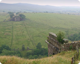
The story of Belah Viaduct: Don’t Look Down
“Good grief!” exclaims Nigel Carmichael as his jaw hits the floor. From the lofty vantage point of a Cumbrian hillside, the retired Signal and Telegraph man peers down on two stone abutments which sit forlornly either side of the valley like a pair of forbidden lovers. When he was last here almost 50 years ago, the air gap between them was occupied by the iron leviathan that was Belah viaduct. But no longer. “It’s just empty, gone, nothing!”
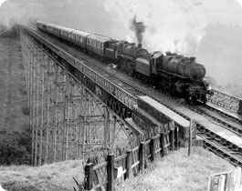
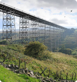
A J2 hauls a train of empties across Belah
Belah was the centrepiece of an ambitious trans-Pennine connection between Barnard Castle and Tebay, involving a tortuous climb up to Stainmore summit, 1,370 feet above the sea. The line was a creation of Thomas Bouch, a talented engineer whose many grand achievements would later be overshadowed by Britain’s most notorious railway disaster.
Bouch was a Cumbrian son, born in Thursby in February 1822 and educated at the local school. He was no great scholar and, aged 16, headed to Liverpool where he accepted an apprenticeship with a firm of engineers. He didn’t settle, soon returning home as assistant to railway surveyor George Larmer – the first rung on a notable career ladder.
It was the age of the train and mania for them was at its maddest. Opportunities abound. Bouch spent four years with the Stockton & Darlington Railway before securing the unlikely post of engineer and manager for the Edinburgh & Northern. He was a month short of his 27th birthday. His pioneering spirit lead him to introduce the world’s first roll-on roll-off train ferries across the Tay and Forth, earning him an enviable reputation amongst his peers.
By the time of his departure from the E&N in 1851, Bouch was already installed as an associate member of the Institute of Civil Engineers. In a consultant capacity, he surveyed and planned a network of routes across Scotland and northern England, amongst them the South Durham and Lancashire Union line through the wilderness of Stainmore.
With the support of industrialists from either side of the Pennines, the SD&LU was conceived as a two-way goods link, moving coal and coke to the blast furnaces of Barrow and iron ore back to Teesside. The sparsity of the population relegated passenger traffic to the role of second fiddle.
Without a murmur of discontent, Parliamentary ascent was granted in July 1857. Nine construction contracts were let, including separate agreements for three iron viaducts. The first, built on stone pillars, carried the line over the Tees at Barnard Castle whilst Deepdale, an iron trestle structure near Lartington, offered views over “a charmingly romantic glen” – rose-tinted terminology from an 1890 journal. But these two were dwarfed by a triumphant 1,040 feet span across a ravine south of Barras, through which flowed the River Belah.
Construction of the wrought and cast iron viaduct got underway in November 1857 when Henry Pease, the new Member of Parliament for South Durham, laid the foundation stone. Costing £31,630, contractors Gilkes, Wilson & Co erected Belah in a little over two years. At 196 feet, it was the tallest bridge in England.
Freight wagons first pressed the sleepers of the 46-mile single line on 4th July 1861, with the passenger service inaugurated one month later. Two trains per day ran in each direction, operated by the Stockton & Darlington. Bouch’s brother William was the line’s Locomotive Superintendent. It was a period of managerial upheaval. Within a year, the line had been absorbed by the S&D which, in turn, was taken over by the North Eastern Railway in 1863.
Traffic levels exceeded all expectations, so much so that the route struggled to cope with the insatiable hunger of Furness’ burgeoning iron and steel industry. As new works sprung up around Workington, the burden grew heavier. The NER board responded in 1870 when authority was granted for the line to be doubled. Within a decade, the annual haul of coke heading west over Stainmore reached one million tonnes.
Those loaded trains felt the strain as they laboured optimistically to the summit. The 13-mile climb from Barnard Castle was rarely flatter than 1 in 67 whilst the ten-mile descent towards Kirkby Stephen was even steeper, with one section falling by 1 in 59.
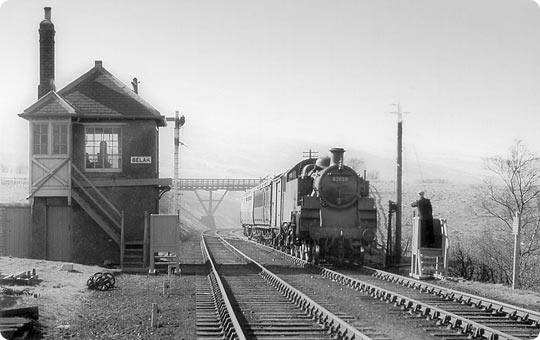
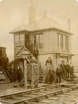
An eastbound passenger climbs past Belah’s box
The line’s success mirrored the fortunes of its engineer. In 1854, Thomas Bouch had submitted a proposal to bridge the Firths of Tay and Forth to directors of the North British Railway. It was dismissed as “the most insane idea ever to be propounded” but, by 1870, the case was overwhelming and work finally got underway on a crossing of the Tay in January 1873. Bouch was at the helm.
It was Britain’s largest single engineering project and, at over two miles, comfortably the longest construction anywhere in the world.
The undertaking was beset by problems. Surveys had indicated a foundation of bedrock but gravel was found instead. Bouch hastily redesigned the structure to lighten the load. Six men died in an underwater chamber. One of the main girders succumbed to the weather and fell into the river. And yet, despite these setbacks, the bridge was completed just a few weeks behind schedule and passed a painstaking inspection by the Board of Trade.
In June 1879, a year after it opened, Queen Victoria crossed the water on Bouch’s bridge and duly rewarded his endeavours with a knighthood. The events of the following winter were tragic and well charted. On Sunday 28th December, both the bridge and a train plunged into the Tay during a violent storm, claiming 75 lives. The subsequent inquiry placed the lion’s share of blame at Bouch’s door, bringing his career to a screeching halt. He died four months after the verdict had been delivered.
Belah though was still standing and did so for 102 years.
As the 20th Century opened its doors, the NER was running five trains either way across Stainmore, connecting Barnard Castle with Tebay in three-quarters of an hour. Specials ran at holiday time through to Morecambe and Blackpool. Durham miners enjoyed the view down the Eden valley en route to their union’s convalescent home in Ulverston.
Like many others, this community service was forced to surrender to the howling blizzards of 1947. In early February, a Darlington-bound night train foundered near the summit. Passengers were transferred to the trailing carriage which was uncoupled and hauled back to Kirkby Stephen. For eight weeks, clearance teams fought the biting weather, assisted by Army flame throwers and a pair of rail-mounted jet engines. Victory was eventually secured by shovel power and elbow grease.
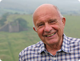
Nigel Carmichael looked after Stainmore’s linewires for seven years
For seven years during the fifties, the unenviable task of keeping Stainmore’s linewires well connected sat on the shoulders of Nigel Carmichael and his mate Albert. Based at Barnard Castle, this pair of adventurers toured the railway by train or Wickham trolley, looking after the signal and telegraph equipment. This often involved working at heights, for which Albert was not well suited as he had a fear of them. Their patch extended up a branch line to Middleton-in-Teesdale and across the Pennines to Merrygill signalbox.
Life in the open air had much to commend it, though its appeal withered during those harsh winters. “It became a completely different world” shivers Nigel. “There used to be a lot of faults – telegraph wires coming down. And that was my job – to climb the pole. My mate used to pull the wires up and I had to join them. Your fingers were frozen! However, you got over it and it got warmer the longer you were up there. Except the toes – they were always cold!”
Belah was a regular haunt. They’d travel up to Barras and walk the last mile, crossing the viaduct to the signalbox by the western abutment. A handful of telegraph wires ran the length of the structure, supported on three-foot long arms extending out from the northern side. A copper binder attached the wires to insulating pots but sometimes, in strong winds, the binder would break and the wire swing out over the drop.
“If the furthest one went, we’d get a stick to try and hook it back. Sometimes I used to go out onto the arm. You never looked down! They provided safety belts but we didn’t use them. You never thought about falling – all you were interested in was getting those wires through and the job completed.” When a train came, the girders would rumble and shake a little, “especially if you were out on those arms and couldn’t get back. The signalman would shout ‘what the hell are you doing there!’”
Nigel delighted in Stainmore’s wildlife, particularly during springtime when the birdsong was at its sweetest. He played delivery boy for one of the signalmen who had a profitable sideline catching rabbits to feed his friends in Barnard Castle. Peewit eggs were also a favoured delicacy. One day he looked down from the girders to see the Belah hounds in pursuit of a fox, closely followed – on foot – by the huntsmen and a handful of platelayers. And a chap called Moscoff once tried fishing from the viaduct. “He had this long line weighted by a great big stone so the wind wouldn’t blow it too much. He didn’t catch anything!”
Despite its isolation, Nigel and Albert were rarely alone. A permanent way gang of a dozen men fettled the track down from the summit. They were often around. And three girls from a remote farm used the track as a walking route to Barras station, where they caught the bus to school.
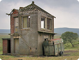
Belah box was a bleak outpost, employing three men and open around the clock. The fire was always burning. Passing trains dropped off lumps of coal together with cans of water to supplement supplies from a nearby well.
Nigel would sit in the window, watching the world go by and putting it to rights. Occasionally the signalman would announce “I’m going out for ten minutes – do you mind looking after the job?”, so Nigel was left pulling the levers. He’d return a couple of hours later saying “sorry, I was delayed!”
Evening entertainment was laid on by an old tramp who’d set up home in an abandoned cottage and appeared regularly in the box. “Fantastic fella” declares Nigel. “He’d been in the Army and the Palestine police, and he’d tell these stories of his time on the road, living in haystacks! I could have listened to him for hours. He had a great knowledge – very well educated – and liked his way of life.”
The livelihood of our S&T duo came under threat as the decline of Britain’s railways gathered pace in the late fifties. “I heard rumours that the line was going to close so I thought I’d better get another job at Darlington.”
Proposals to withdraw Stainmore’s passenger services spoiled the Christmas party of 1959. Local forces were marshalled and a petition marked the start of a vociferous campaign, aimed at securing a reprieve. Ultimately the quest was futile. The remaining coke traffic was soon diverted via Carlisle although the line’s new diesel units continued to carry travellers for another couple of years.
The closure programme finally claimed Stainmore on the 20th January 1962. Four hundred enthusiasts jemmied themselves onboard a double-headed steam special, bedecked with a wreath and accompanied on bagpipes by the melancholy sounds of Auld Lang Syne.
It was the end of the line for Belah. Piece-by-piece, in an act of extraordinary vandalism, its ironworks were dismantled and salvaged for scrap. A year after the axe fell, one of the railway’s greatest engineering masterpieces had been cut from the landscape.
Part of the route still clings to life through the exploits of volunteers from the Eden Valley Railway, who operate tourist trains between Appleby and Warcop. Their official aim – though clearly a pipe-dream – is to relay track across the moors and reconnect Barnard Castle with the railway network. This mind-boggling aspiration would involve a £25million investment at Belah.
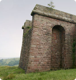
For those who can’t wait for pigs to fly, three survivors of Belah’s past await the attention of folk on Shanks’ pony. Two colossal abutments – notable feats in themselves – still mark the extent of the former span whilst the tattered remains of the signalbox, abandoned by the maintenance men, have withstood the ravages of forty Stainmore winters. Footpaths pass beneath these relics, within 400 yards of public, if rather minor, roads.
As Nigel muses, “I thought this railway would last forever but, with modernisation, it’s all gone.” And the Belah valley is palpably poorer for it.


 November 2009