


Loch Ken Viaduct
Loch Ken Viaduct
The Portpatrick Railway was intended to form part of a trunk route connecting London and Belfast by railway, via the twin ports of Portpatrick and Stranraer. The line was granted Parliamentary approval on 10th August 1857 and the section from Stranraer to Castle Douglas became operational on 12th March 1861. Amongst its principal engineering feats was a viaduct over Loch Ken which was built under a separate contract by Thomas Nelson & Company of Carlisle at a price of £12,288 13s. Responsible for the design were B & E Blyth, consulting engineers.
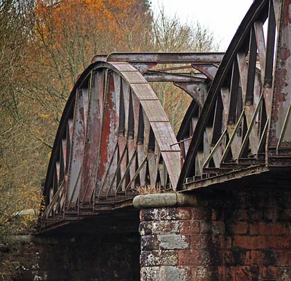
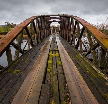
The structure incorporated a curve of half-a-mile in radius and carried a single track over the water at an oblique angle. The depth of the loch at the point of crossing is 29 feet in summer. The viaduct consists of seven spans: three of 130 feet featuring wrought iron bowstring girders, two semicircular masonry arches of 20 feet span within the abutments and two openings of 20 feet at each end provided with flat cast iron girders. As a result of there being scarcely any current, it was deemed unnecessary to set the piers in line with the water flow; instead they are placed at right angles to the railway, with each pair of girders at a slight angle to the adjacent ones.
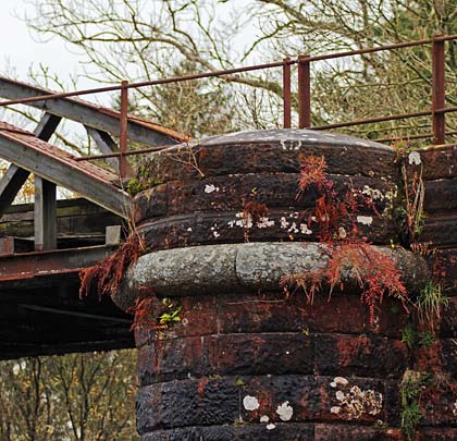
The foundations consisted of strong gravel, except in the case of the eastern abutment for the main spans where a running sand was met with, requiring the lower courses of the masonry to be laid on a bed of hydraulic lime concrete, 2 feet thick. The two deep-water piers are each formed of two towers, 8 feet in diameter, placed 8 feet apart and connected above water level by semicircular masonry arches.
For each tower a cast iron tube, in six sections, was sunk. The tubes were 36 feet and 42 feet in length for the east and west piers respectively. When the masonry was brought up to the surface, the upper castings of the tubes were then removed. Around the piers, 4,000 cubic yards of loose rubble was deposited so as to produce an artificially deeper foundation. The tubes sank from 1 to 2 feet under their own weight, until they reached the gravel and sand. This formed a good test of the foundation as the weight of the tubes on their narrow edges was the equivalent of 8 to 9½ tons per square foot, while the total weight on the foundations of the finished structure – including the moving load – was only about 6¼ tons per square foot.
To sink the tubes, two plate-iron screw pans of an inverted cone shape were used. There were openings in the sides, covered with leather flaps, to prevent material from escaping when the pans were filled. Three arms of round iron projected through the sides of the pans and, being connected to a long rod with a cross handle at the upper end, the screws could be worked by four men. When full they were raised by tackle. By this method the tubes were sunk in some instances as much as 18 inches per day, the minimum being 2 inches in a day with the west pier’s northern tube where large boulder stones were encountered, rendering it necessary to use a screw pick. When the tubes had been lowered the required depth, concrete was poured into them, varying from 12 feet to 18 feet in depth. Ashlar masonry was then laid on the concrete, the cordon course being of granite in large blocks for receiving the ends of the girders, which rested on wrought iron plates laid on thick sheets of vulcanised India rubber to lessen the effect of vibration.
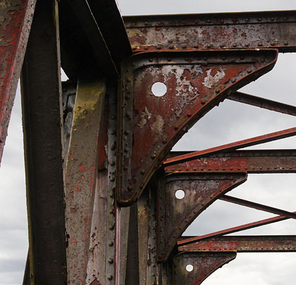
The bowstring girders are 136 feet 8 inches in length, rising 17 feet 6 inches. The sections of the upper and under booms are identical, consisting of a main plate, 24 inches wide and ¾ inch thick, and of two channel irons each 8 inches by 4 inches in section and ½ inch thick, placed 8 inches apart, between and to which the struts and ties were riveted.
The transverse girders for carrying the track are 6 inches in depth at the ends where they rested on the channel irons of the under booms, and 15 inches deep in the centre. The middle web of these girders was ¼ inch in thickness. Each alternate girder projected 2 feet from which T-shaped iron struts were carried up to the crossings of the diagonal bracing.
The weight of the girders and roadway between the points of support was 88 tons, making a total dead load of 102 tons with the ballast. Taking the rolling load at 1 ton per lineal foot, the total load on one span would be 232 tons. When the whole of the load was on the girders, there was no compressive strain on any of the diagonals, but there were tensile strains varying from 3.4-7.5 tons.
The girders were built in position on staging and the greatest amount of deflection of any one girder from its own weight was ⅜ inch. Subsequently, when a 34-ton locomotive was placed in the centre of each span and run over at 10mph and then 25mph, the deflection amounted to no more than ¼ inch. When four engines were coupled together, giving a load of 1 ton per lineal foot, the deflection only amounted to ⅝ inch. Board of Trade inspector, Captain H W Tyler, expressed particular satisfaction with the design and construction.
Loch Ken viaduct was the scene of an accident on 30th December 1935, when a mixed goods and passenger train derailed at its western end, although no damage or injuries were sustained.
During the Second World War, the port of Cairnryan was purpose-built as No.2 Military Port, with three harbour piers and a railway linking it with Stranraer. Millions of tonnes of ordnance and supplies came into the UK, much of it being transported over the viaduct. Then, in 1943, the railway also helped to move US troops.
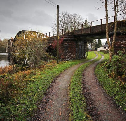
The line failed to survive the Beeching cuts, closing on 14th June 1965. The viaduct is now in private ownership, but still acts as a vehicular route across the loch to connect dwellings on the west side with the main road. For this purpose the waybeams have been renewed.

 August 2013