


Civil Engineer William Cudworth describes the construction of... Hownes Gill Viaduct
Civil Engineer William Cudworth describes the construction of… Hownes Gill Viaduct
Hownes Gill Viaduct was situated near to the Consett Ironworks of the Derwent Iron Company, in the north-western part of the county of Durham, on what was formerly the Stanhope and Tyne Railway, an undertaking which came into the hands of the Stockton and Darlington Railway Company in the year 1844. Hownes Gill was a dry ravine 800 feet in width and 160 feet in depth, and originally the line was laid out with gradients corresponding with the natural contour of the ground, that on the west side being 1 in 2½, and that on the east side 1 in 3. The traffic was conveyed over these gradients for some years with little difficulty; but a large accession of trade, due mainly to the discovery of the Cleveland ironstone, rendered greater facilities of transit imperative. It then became apparent that the erection of a high-level viaduct was indispensable; and as early as the year 1844, the directors of the Stockton and Darlington Railway Company took steps with the view of ascertaining the probable cost of such a structure. It was not, however, until December 1856, that a contract was entered into with Mr John Anderson, to erect a viaduct of firebrick set in hydraulic mortar and the arches in cement, in 18 months, and to uphold it for twelve months after completion for the sum of £14,614. The design was prepared by Mr Thomas Bouch, M Inst C E, and was subsequently approved, with some modifications, by the late Mr Robert Stephenson and Mr G P Bidder.
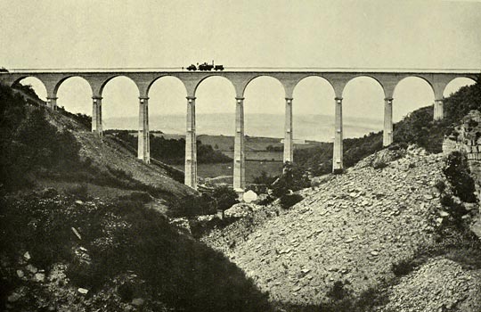
The extreme length of the viaduct was 780 feet, and its greatest height from the bottom of the inverts to the level of the rails 162 feet. It had 12 semi-circular brick arches, each 50 feet span, 14 feet in length, and 2ft 6in in thickness. The inverted arches in the foundations, four in number, which were introduced at the suggestion of Mr Stephenson, so as to extend the bases of the three central piers until the weight scarcely exceeded 1 ton per superficial foot, had a versed sine of 14 feet, were 38 feet in length, and 3 feet in thickness. The extreme height of the five loftiest piers, measured from the springing of the inverts to the springing of the arches, ranged from 114 to 110 feet; that of the six remaining piers diminished rapidly towards each end. Their length was 14 feet at the top, and 38 feet at the bottom, the latter dimension corresponding with that of the inverts. The piers to within 15 feet of the inverts were stayed by buttresses transversely to the line of the viaduct. At this point they were only 17ft 6in in length, but below this level the buttresses merged into the piers, when they together had a rectangular section 38 feet in length. The buttresses were 3 feet thick at the top, and 5 feet thick at the bottom; their projection from the piers being increased by offsets at intervals of 35 feet. The piers, although light in their proportions, were reduced by recesses, (7ft 3in wide and averaging 3ft 9in deep) sunk in each side, so that the horizontal section of each pier with the buttresses was in the form of a double cross, the brickwork in the middle being only 2 feet thick. These recesses were not continuous, but were divided into three compartments in height, and by their adoption the amount of brickwork in each pier was reduced about 14½ per cent.
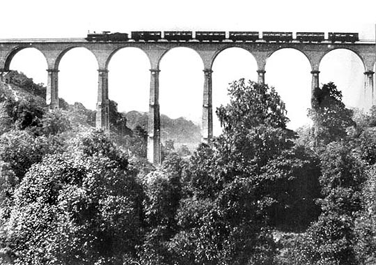
Between the spandrel walls, two internal parallel walls of stone were introduced to sustain a platform of flagging, on which the waybeams and the ballast were carried. The waybeams, which were of Memel timber, were at first secured to the internal walls by bolts; but as this plan was found to be objectionable, the nuts from the holding down bolts were removed, and a thickness of 6 inches of coke ballast was interposed between the waybeams and the flagging. The parapet consisted of a substantial cast-iron railing. The firebricks, which were of excellent quality, weighed 9lb 11oz each, and cost the contractor at the viaduct 31s 2d per 1,000. The number used was 2,665,000. It was a gratifying fact that the work was completed without accident, and that not a single crack was to be found in the whole of the structure. The erection of the scaffolding, which was of a very light character, was considerably facilitated by the hoisting tackle being made to traverse a stout wire rope stretched across the gill, and firmly fixed at each side. When the arches where about to be turned, the piers were stayed by two parallel wire ropes stretched from end to end of the viaduct.
The first brick was laid in February 1857, and the first train passed over the viaduct in July 1858. The cost of the structure amounted to £15,756, the contract sum having been increased by the additional depth of the foundations, by the adoption of a heavier parapet, and by other contingencies. Regarding the viaduct as an unpierced solid, its contents would amount to 61,910 cubic yards, and its cost would be 6s 1d per cubic yard.
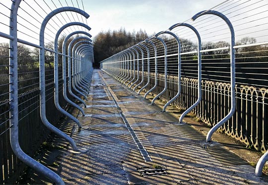
Photo © Rick Garside
The question of the relative cost of brick and iron viaducts was then alluded to, reference being made to two works of the latter description erected by Mr Bouch on the South Durham and Lancashire Railway. These viaducts consisted of three lines of trellis girders resting upon skeleton piers, formed of six cast-iron columns, jointed at intervals of 16 feet, and braced together by horizontal cast-iron struts, and by vertical and horizontal tie bars of wrought-iron. The clear spans between the piers were in all cases 48 feet. The Belah viaduct was 1,000 feet in length and 197 feet in extreme height. The Deepdale viaduct more nearly resembled Hownes Gill in its proportions, being 740 feet in length and 160 feet in extreme height. A comparison was therefore instituted between the probable cost of such an iron viaduct erected across the Hownes Gill valley, and one of brickwork, supposing both to be built to carry a double line of railway, and that the spread of the foundations was in each case adjusted to sustain a weight of 21 tons per superficial foot, including the greatest moving load. The price of the brickwork and of the masonry were taken from Mr Anderson’s schedule; those of the timber and ironwork were the price actually paid to Messrs Gilkes Wilson and Co, the contractors for the South Durham and Lancashire viaducts, minus a deduction of 10s per ton for the cost of cartage over country roads. With this adjustment it was found that the cost of the viaducts, calculated in this way, would be £20,681 for the brick structure, and £16,249 for that of iron. It was thought probable that the interest on the difference between these two amounts, say £222 per annum, would be absorbed in the periodical examination and painting of the iron, and the depreciation of the perishable timber platform; and that at the place referred to a brick viaduct would be, ultimately at least, as cheap as one of iron. If the viaducts were designed to carry a single line of railway, the comparison would, it was believed, be still more in favour of brick. Although the author preferred brick or stone, he by no means regarded iron as ineligible under all circumstances. In situations which did not yield suitable building materials, and where there were no cheap means of conveyance from a distance, the small relative mass of an iron viaduct would be a strong argument in its favour; for the whole weight of such a structure, including masonry foundations, would be less than one-fifth that of brick. This circumstance would also conduce to the selection of iron in cases of doubtful foundations.
25th November 1862
More Information
| Engineering Timelines | A short overview of the viaduct |
