


Crumlin Viaduct Handbook
Crumlin Viaduct Handbook
Opening of Crumlin Viaduct
The erection of that magnificent structure, the Crumlin Viaduct, has brought into the secluded locality in which it stands thousands of persons interested in witnessing this achievement of engineering skill, or in contemplating the bold and picturesque scenery surrounding the village from which the viaduct takes its name. The numerous inquiries made by visitors in reference to the viaduct and its locality have led the writer to infer that a small handbook, containing the desired information, would be useful and acceptable. He has, in the following pages, endeavoured to meet this requirement, giving sufficient detail as to the formation, dimensions etc of the viaduct, to enable the scientific reader to appreciate the adaptation of its several parts, and to form an adequate conception of its vast proportions, and as much descriptive matter of a less technical kind as the general reader would care to peruse. It may be added that the more scientific portions of the following pages have been compiled and enlarged from a paper which the author had the honour of submitting to the South Wales Institute of Engineers, in the early part of the year 1860, and which was based upon the actual data prepared for the erection of the viaduct. He submits this handbook to the public, aware that the eye of the critic may detect evidences of inexperience in literary labour; but trusting that it may, nevertheless, aid the visitor to Crumlin in taking an intelligent interest in the attractive objects which are here described.
The locality of the bridge
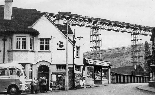
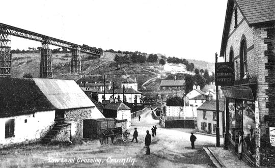
Before the introduction of railways into the neighbourhood, Crumlin was a secluded, and comparatively unfrequented village, scarcely known to any beyond the limited number of persons resident there, or interested in the products of its vicinity. Seated in one of the most picturesque spots in the county of Monmouth, and surrounded by natural features of unsurpassed loveliness, it was, only a few years ago, a rude hamlet, possessing no attractions save those derived from its situation, and consisting only of a few miners’ cottages, the Navigation Inn, and the company’s shop.
It has been said that Crumlin derived its name from “Cromlech”, a designation given to Druidical monuments. These cromlechs were usually placed in the centre of a circle of stones composing the Druidic temple, and sometimes having a single stone of large size near them, supposed to have served as a pedestal for some deity. But no traces of such a monument are to be found at Crumlin at the present time.
The village is situated in what is geologically termed the South Wales coal basin; and in the neighbouring quarries are often found fine fossils of calamites, lepidodendrons, and in the shale, fossil ferns and other cryptogamic plants. It is distant from Pontypool four and a half, and from Newport twelve miles. Since the commencement of the noble viaduct which now stretches across the valley just over the village, the population has rapidly increased, and there has, of course, been a corresponding addition to the number of dwellings; while the permanent establishment there of the viaduct works, has given an unwanted degree of importance to the village. It has, also, become increasingly known from being situated at a point where two important railways intersect each other. The one, the Western Valleys Railway of the Monmouthshire Railway and Canal Company, runs from the port of Newport through the charming valley traversed by the river Ebbw, to the great iron works of Blaina, Nantyglo, Ebbw Vale etc, lying about seven or eight miles above Crumlin. The other is the line of railway in which the Crumlin Viaduct forms a connecting link on the great road from Cardiff to Merthyr, or to Chester and Liverpool and the north, formerly known as the Taff Vale Extension of the Newport Abergavenny & Hereford Railway, but now called the West Midland Railway, Newport section.
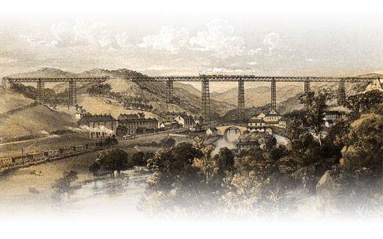
In close proximity to the village stands the stupendous and elegant work of art, the Crumlin Viaduct – a remarkable monument of ingenuity and skill, and which has attracted many thousands of visitors from all parts of the world to this previously unfrequented locality. Simultaneously with the building of the viaduct, Messrs Kennard erected permanent workshops, and subsequently places of worship, a reading room, and agents’ and workmen’s houses have risen to meet the requirements of the largely-augmented population. Mr T W Kennard, under whose direction the viaduct was constructed, has also built a fine mansion in the immediate neighbourhood. It is in the Swiss style of architecture, from designs by Mr Owen Jones. These new features, all resulting from the skill and enterprise of the gentleman to whom the erection of the viaduct was entrusted, have given a phase of unwanted activity to Crumlin, as well as diversifying with the products of art and industry, the delightful rural scenery of the valley. The viaduct is hemmed in by lofty hills, thickly clothed with various shrubs and trees on either side, with here and there richly cultivated spots, adjacent to neat cottages and gardens peeping out amidst the foliage – some at the summit of the hill, and others half-way up the steep, approached by paths winding through verdant avenues, or amid irregular and rocky declivities. The lofty hills touched by the extremities of the viaduct, cast their shadows upon the river Ebbw, which pursues its tortuous course in the valley below; and in the summer months, when this stream and the canal which runs parallel with it glisten in the sunshine, the neighbourhood of Crumlin Viaduct presents scenes of unsurpassed natural beauty. The towing-path along the canal affords a pleasant walk for many miles, and reaches – about a quarter of a mile distant – a spot from which the tourist may obtain an excellent view of the viaduct, Crumlin Hall and surrounding objects.
About half a mile beyond this point the visitor comes to the quiet village of Newbridge, whence the charming scenery of the valley may be seen to great advantage. At Newbridge is an inn which, though possessing no architectural pretensions was favourably known among travellers as a snug and comfortable hostelry, “long, long ago,” ere railways had superseded that “ancient institution”, the stage-coach. From this inn, still resorted to with satisfaction by the tourist, the village takes its name. The inn is mentioned in the Rev W Arthur’s interesting memoir of Mr Samuel Budget, “The Successful Merchant”, that gentleman having stayed there on his way to the principality. Speaking of the natural beauties of the neighbourhood, he says “We think the scenery quite equal to the lakes of Westmoreland.”
Assuming that the visitor has walked to Newbridge by the canal path, he will find it pleasant to return to Crumlin by the old tram-road, for which he must inquire while at Newbridge.
The visitor from Newport, if time permit, should alight at Newbridge Station, and pursue the path to Crumlin along the canal bank – a rural and exceedingly pleasant walk of about half a mile.
At Crumlin the tourist may obtain the convenience of railway transit to Caerphilly Castle, Raglan Castle, or the other places of historic interest with which Monmouthshire and adjacent counties abound; while such as desire to prolong their stay at Crumlin, taking it as a focus whence to enjoy pedestrian or other excursions, may find ample accommodation at the Viaduct Hotel.
The design
It was a work of much consideration and care to adopt the most economical and efficient means of crossing the Crumlin Valley. Making a bridge of iron in the most economical manner became the work of one more directly conversant with works in iron than are the generality of railway or civil engineers.
The company’s Board of Directors called upon several gentlemen to tender for a bridge to cross the valley upon their own designs respectively. Mr Thomas William Kennard was the successful competitor, and it is his design which has been so effectually carried out under his own direction.
After careful consideration of the cost of building large masonry piers of the necessary height and dimensions, it was determined that Mr Kennard’s plan of open cross-braced iron pillars would be cheaper and more suitable; and it was found by estimating the cost of a number of different designs, that the distance across the valley could be most economically divided into ten equal spaces, or spans, of 150 feet each. If the spans had been less a greater number of piers would have been necessary, and although less iron would have been required in each span, by reason of the smaller dimensions of the various parts in them, the cost of additional piers was found to overbalance this saving of material; had they been larger fewer piers would have been required; but for larger spans calculations showed that the increased dimensions of iron in the various parts necessary for such spans would have increased the weight at a much greater ratio than the saving effected by a reduced number of piers. Thus the dimensions have been economically designed and adjusted by a series of laborious and tedious calculations.
Dimensions of the viaduct
The length of ironwork is 1,500 feet; but including abutments of masonry, the length is 1,658 feet. Height, 200 feet; or from top of handrail to underside of foundations, 208 feet.
Description of the viaduct
Commencement of the works, foundations, fixing first column etc
Previous to determining the exact spots for the piers, a series of borings and trial holes were made to ascertain the nature of the ground. In the bottom of the valley was found, for a distance of upwards of 40 feet from the surface, a bed of alluvial soil, chiefly hard gravel, which was considered sufficiently hard and solid for the foundations of such piers as could not be placed on rock.
The centre of the canal was fixed upon as the site of one pier, and as the spot to commence operations, from which the distances for other piers were set out. The canal communicating with Newport, formerly terminating a short distance beyond the viaduct northward, was stopped off by a dam and pumped dry, the earth within excavated to the solid gravel, a depth of 14 feet from the surface, which was filled up with the foundation formed of about 1 foot thickness of concrete, upon which was laid a course of 4″ close Memel timber planks, and on these a solid course of masonry 12 feet thick, terminating even with the surface of the ground. The masonry immediately under the pillars is in blocks not less than 1 foot thick, and the surfaces finely dressed and jointed, and laid in Portland cement; the outer edges of the stone are left rough as they came from the quarry. The same description of foundation will, with few exceptions, apply to such others as are not on the rock; those on the rock are of the most simple description, formed by levelling its surface, upon which the iron is bolted. The foundation of the pier situated in the canal having been completed, the day was fixed for formally erecting the first column, or first piece of iron-work, on the 8th day of December, 1853, which was done by Lady Isabella Fitzmaurice, who, in the presence of the Directors, several of the gentry of the neighbourhood, and persons interested in the work, placed beneath it, in a recess in the stone, a cup containing coins of the current date, after which the permanent bolts were put in, and the work formally commenced. A bottle of wine was broken over the spot, and this pier was called the Isabella Pier.
The cup bore on the outside the following inscription: “Crumlin Viaduct. This column was erected by the Hon Captain Fitzmaurice, chairman, assisted by the Hon Mrs Fitzmaurice, Lady Isabella Fitzmaurice, and T W Kennard Esq. December 8, 1853.”
The piers
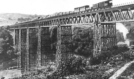
The piers are remarkable as a combination of lightness and economy of material, with strength and facility for erection.
A description of the Isabella Pier, it being one of the highest, will apply to all, as they only differ in height. It consists of fourteen hollow cast-iron columns, 12 inches external diameter, arranged in the form of an irregular hexagon. The two columns are of metal 1 inch thick, all the others are ¾ inch thick; each column is 170 feet long, consisting of ten lengths, each 17 feet, connected by bolts passing through lugs cast on outside; a projection of ½ inch is formed on one end of each, which fits into a corresponding recess inside the adjoining length; all are accurately turned and fitted at the joints; the bottom rests on a short piece of column jointed in similar manner, and formed into a base-plate 3 feet square, and is 2’3″ high, strong 1″ feathers cast outside to distribute the pressure of column upon the base-plate. The base-plate is fastened to the masonry or rock by ragbolts 12 inches long, let into the stone, and secured there by pouring in the interstices molten brimstone. The top or head of each column is formed into a cap 2 feet square, 1 inch thick.
The columns are all connected together by a system of horizontal bracing, which occurs near each joint, or at the top of each length, or tier, of columns, and consists of cast-iron distance pieces of a girder form of section, with a flange running through its centre, and called “distance girders”; they are 12 inches deep, 5 inches wide, and ¾ inch metal; the columns are formed octagonal at this part so as to present a flat surface, to which the distance girders are secured by bolts passing through the columns. The distance girders are tied together diagonally by 1½ inch round wrought-iron bars, eight in each tier, and in the same horizontal plane; they are secured inside the columns with keys or cotters. The distance girders connecting the bases of columns are of larger dimensions – namely, 18 inches deep, 6 inches wide, and of thicker metal.
Between each of the columns there are two vertical wrought-iron bracings, 4 inches wide, ½ inch thick, or seventy-two bars in a tier, which are fastened by a pin at each end of 14 inch diameter, which connects it to the distance girder, in which pockets of suitable form and dimensions are cast to receive the ends of bars. Each bracing bar is connected with the distance girders at one end by two short pieces of the same size bar – namely, about 18 inches long, in which an elongated hole, 3″ x 1″, is formed corresponding to a similar hole in the bracing bar; the latter is secured between the two short pieces by a gib and cotter, which can be tightened so as to adjust the length of the bar to suit the work.
Triangles surmount each of the piers, and rest upon the caps formed on top length of columns, to distribute the pressure of the superstructure evenly over the whole of the columns; each set consists of a strong cast-iron framing composed of three longitudinal girders 2 feet deep, and eight transverse ditto binding the heads of the columns together, and forming a base upon which are fixed cast-iron triangular framing pieces, 14 feet high, of suitable form and section to receive the main girders, which carry the floor, and take their bearing only at the apex of each triangle. Four triangles forming a set are united by wrought-iron vertical bracing bars 4″ x 1″ in.
It will be seen that only two out of the fourteen columns of each pier are placed vertical; all the others are inclined inwards, the greatest inclination being about 1 in 12.
In constructing the piers it was necessary to make arrangement by which the main girders could be lifted at the centre, therefore the piers were built to the requisite height without the distance girders leaving a parallel opening 5 feet in width throughout the height. Within this space, at the bottom of it, the main girders were built. They were of sufficient length to reach nearly from centre to centre of piers; and after they were lifted to top of piers, the distance girders were fixed with the bracing bars connected to them. The sectional area of acting metal in the columns of one pier is about 400 square inches, and the maximum strain on the iron under test load is less than 1½ tons per inch.
The advantages offered by iron piers over masonry are –
- Simplicity in erection and construction, as all the materials can be prepared and fitted before they are brought to the spot, and no expensive scaffolding is required. They are so arranged that each length of columns can be completed, and a few planks laid upon them forms a good even floor, and convenient to proceed with the next length. The materials are drawn up by a common windlass, and, as the heaviest piece does not exceed one ton in weight, can be easily fixed by common sheer legs and pulleys.
- The rapidity with which these iron piers can be built – a pier 200 feet high can be completed in ten or eleven weeks, while a masonry pier of the same dimensions about as many months.
- The amount of pressure on the foundations in some situations is an important consideration. Mr Kennard’s iron pier is remarkable for its lightness, and consequently a small amount of pressure on the foundations.
The following estimate shows the weight on the foundations of Isabella Pier of the Crumlin Viaduct, and what may be fairly calculated for a stone pier of suitable dimensions –
| Weight on foundation of iron pier | Weight on foundation of masonry pier | ||
| Iron | 200 tons | Masonry | 2900 tons |
| Superstructure | 100 tons | Girders etc | 100 tons |
| Passing load | 300 tons | Passing load | 300 tons |
| Total | 600 tons | Total | 3300 tons |
The base of the iron pier is about 40 feet x 30 feet, or 1,200 superficial feet, therefore the pressure on the foundation is about half a ton per superficial foot, while that of masonry pier must be at least five times as much.
The saving in the cost of iron piers may be safely estimated at a third less than masonry, as may be seen from the following estimates –
| Cost of an iron pier | Cost of a masonry pier | ||||
| 163 tons castings | @ £15 | £2445 0s | 2197 yards excavation | @ £18 6d | £164 15s 6d |
| 7 tons wrought iron | @ £18 | £126 0s | 1041 yards masonry footings | @ £1 5s | £1301 5s |
| 1128 yards excavation | @ 1s 6d | £84 12s | 2120 yards | @ £1 5s | £2650 0s |
| 1400 cube feet Ashlar masonry | @ 3s | £210 0s | Total | £4116 0s 6d | |
| 42 yards concrete | @ 8s | £16 6s | |||
| Total | £2881 18s | Difference in favour of iron pier | £1234 2s 6d |
Since the erection of the Crumlin Viaduct piers, several other viaducts have been built with open cross-braced iron piers, all more or less like these. The author is not aware of any having been used previously.
The girders and superstructure
The main girders, or supporting beams of the floor, four in each span, or forty in the whole viaduct, are formed exclusively of wrought iron, upon the principle known as Kennard and Warren’s patent. Each girder is built of bars, plates and angle iron riveted together, forming a truss composed of seventeen equal sided triangles; total length, 150 feet, and extreme depth, about 15 feet 6 inches. These girders are arranged 9 feet apart, centre to centre, and connected to each other in pairs, and placed in such a position that the centre line of railway coincides as far as practicable with the centre line of the pair of girders over which it passes. As there are two lines of railway, two pairs of girders are placed at a distance of 6 feet between them, making the total distance from outside girder to outside girder 24 feet: upon these are laid a planking of 6 inches thickness, of creosoted Baltic timber, secured to the girders by bolts, and forming a platform 26 feet wide between the hand-railing. Upon this platform are laid the longitudinal sleepers of the railway, secured by bolts passing through the platform. The rails are of double head section, held in cast chairs so formed as to hold a guard-rail to prevent wheels running off the line. The hand-railing is formed of cast-iron bolted to the platform, and is of very light construction, weighing about 25lbs per lineal foot.
The only points from which the girders receive support are at the apexes of the triangles where they rest upon wrought-iron turned pins 3¼ inches diameter, about 9 inches long, passing through the end of each girder, resting on a cast-iron saddle of suitable shape, and dimensions to fit the end of girder, and a groove formed in the apex of the triangle; this pin forming a hinge by which each end of each girder is secured to the top of the pier upon which it rests.
Details of the girders
The top flange, or compression bar, is formed cellular; it is 14 inches deep, 9 inches wide, built of four bars angle iron 6in x 2½in x ½in, two plates 9in x ⅜in, and four ditto 6in x ½in; all 16 feet long, riveted throughout with ¾in rivets, 5 inches apart, centre to centre, of rivets: the whole making up a sectional area of about 35 square inches. Every 16 feet length on either side the centre length is reduced in thickness; the sectional area of the end length is about 23 in; all the joints are covered inside and outside, and occur at the intersections of the diagonal struts and ties.
The bottom flange or tension bar is formed of flat bars. It consists of four bars 6in wide, and two bars 4in wide, all 1in thick at the centre, giving a sectional area of 32in; or, by deducting for rivet holes, the effective section left is 26in. The thicknesses of bars are reduced towards each end of the girder, when they are ⅝in and the 4in bar is omitted, reducing the sectional area to about 15in and the effective section to 12½in. The bars are all of the same length, namely, 16ft 4in, excepting the end bars, which are 17ft 2in; the joints are formed by covering plates 2ft long, 16in wide, of suitable thickness to make the same section as the bars; they unite and are riveted.
The diagonal ties are each formed of two bars 9in wide, the end tie being ¾in thick, the next ⅝in, and the next ½in: they are all connected with the tension and compression bars, by very accurately turned wrought-iron pins, varying in diameter from 3¼ in to 3 in, which pass through holes carefully bored to fit. As great accuracy was necessary in boring these holes, Mr Kennard constructed boring machines to make four holes at once, and at the proper distance apart. The diagonal struts and ties at their upper ends pass inside the compression bar; a slot hole in the bottom plate thereof is made for this purpose where it is required.
The thickest or end struts consist each of four bars 5in x ⅝in, and four angle irons 2½in x 2½in x ⅜in, secured by rivets 5in apart, giving a sectional area of about 20 square inches; those struts near the centre of the girder are reduced in thickness to a sectional area of about 10 square inches, by reducing the thickness of metal.
The horizontal cross-bracing, which connects the girders in pairs, consists of a number of cast-iron distance tubes, 6in external diameter, 1in thick, formed with ends suitable to fasten to the projecting ends of the pins which connect the diagonal struts and ties to compression and tension bars; the ends of these pins have a cast washer attached by a screw, and to these washers the distance tubes are attached; the diagonal bars, 3in by ½in, are united to them by pins passing through the cast distance-tubes in a similar manner to the bracing in the piers, as previously described. They can be tightened in the same way by gib and cotter arrangement.
The riveting of compression bars and struts, wherever practicable, was performed by machine, which is still in use at the viaduct works, and is found far superior to hand riveting, both in respect of quality and quantity of work done; in proof of the quality, several pieces of hand and machine riveting have been planed through the row of rivets; it is found the pressure of the machine causes the rivets to fill the holes, which is not always the case in hand riveting, and the expense is found about a fifth of the cost of ordinary hand-work.
The distribution of material in the girders
The economy of material in these girders is worthy of notice, and, compared with some other railway bridges of similar span, is very remarkable; the weight amounting to less than 6cwt per foot run, would lead us to think a great strain upon the iron would be produced by a full load, whereas this is not the case, the maximum compression strain being 4 tons per square inch, and in tension 5.5 tons per square inch. A great many bridges have come under the author’s notice, none of which appear so economically designed as this, and several of recent construction weighing 8cwt per foot run per pair of girders of similar span, or 64½ tons per span. The following is the carefully estimated weight of a pair of Crumlin Viaduct girders –
| Tons | cwts | qrs | lbs | ||
| Tension bar | 11 | 15 | 1 | 16 | |
| Compression | 13 | 6 | 0 | 26 | |
| Struts | 7 | 11 | 2 | 16 | |
| Ties | 3 | 16 | 3 | 22 | |
| Bracing | 4 | 11 | 3 | 20 | |
| Pins, bolts, rivets, etc | 2 | 15 | 2 | 0 | |
| Bearing blocks | 0 | 2 | 1 | 12 | |
| Total | 44 | 0 | 0 | 0 | per pair of girders |
Strains on the girders
Mr Kennard’s method of ascertaining the amount of strain upon the various parts of the girders is very simple and practical, and it applies to all girders of this description, by which he is enabled to proportion the material at the various proper parts. It may be described as follows –
Assume the weight for a pair of girders, including the floor, railway, and heaviest load that will be passed over them, to be 270 tons evenly distributed; the half of this weight, or 135 tons, will be supported by each girder, and distributed. Thus, 135/9=15 tons to be supported on each division of the top flange; the top flange being considered inflexible between the points of support, or intersection of the diagonal, may be considered as nine separate beams, each 15 tons weight, supported on the points of the triangles formed by the diagonal struts and ties.
The girders are not always under equally distributed loads. On the approach of a train to the centre, only half, or a part, of the girder is loaded, the other half being without, causing variation in the direction and amount of strain on the diagonals. Some of those which are wholly in tension when the girder is equally loaded being brought into compression, and vice versa.
The amount of strain on top and bottom flanges can be found from the principle of the bent lever, the proportions of such lever are as the depth of girder being one arm, and half the length of span being the other arm; thus, the depth of girder being 15.5 feet, and half the span 75 feet, are in the proportion of 4.8 to one, and this multiplied by ¼ of the distributed load on a girder, gives the strain at centre.
For example, we have taken in previous considerations of strain a distributed load 270 tons for a pair of girders, or 135 tons for one girder; therefore, 135/4= 33.7 x 4.8=161 tons strain at centre. This, however, is not the strain at centre of the Crumlin Viaduct girder, it being arrived at from an assumed weight for a pair of girders, which, to avoid troublesome figures, is made greater than the strain which actually exists, namely, about 144 tons. The strain at intermediate parts between the centre and end of girder will be in proportion to the distance of such parts from the centre.
Expansion and deflection
The variation in length of the girders after they were made continuous by connecting the top flanges where they meet over the piers, thereby forming four continuous tubes the whole length of the viaduct, was at one time very troublesome; a subsequent alteration in some detail of the bearings upon the masonry abutments at each end, by which ample room and provision was made to allow free motion, removed the difficulty.
A careful record of the variations in length, caused by variable temperature from day to night was for some time kept, and the greatest amount of diurnal expansion, or contraction, observable in the seven spans – which, being united, formed a continuous compression bar, 1,050 feet in length – was 7/16ths of an inch, the observation being taken at 4am and 4pm on the 12th of June, a fine, warm day, but cold, damp night. The greatest difference in length recorded is from February 12th, 1861, the temperature of girders being 32°F, to the 27th August, same year, when the temperature was 90°F, there being a difference in temperature of 58°, giving an increase in the length of 2¾ inches, or about .0474 of an inch for every degree of heat. From this observation, a simple rule for finding the expansion and contraction of other bridges may be formed, namely, for every degree Fahrenheit of variation in temperature there will be, practically speaking, 1/260000ths of its length of expansion or contraction, thus for a girder 100 feet long say 100×12=1200 inches, and 1200/260000=.00460 of an inch for one degree, or for 58 degrees there will be .00460×58 or .2668 of an inch variation in length, or a little more than ¼ of an inch.
The Crumlin Viaduct girders are fastened to the iron piers, which, being of great height, are slightly flexible; therefore, the motion of expansion and contraction of the girders causes a corresponding lateral deflection. It has been ascertained by experiment that the elasticity of the iron-work is sufficient to allow the piers to deflect several inches without permanent set or injury.
The deflection of the girders caused by a passing train, heavily loaded and travelling at the usual speed over the viaduct, has been observed after constant traffic of several years, and it is ⅝ths of an inch – the girders return to their exact form immediately the train has passed; this is easily ascertained at any time by a wire suspending a weight from the girders and attached to a sliding scale, fastened to the ground below.
Deflection from testing
In the month of May 1857, the whole viaduct was tested in the presence of Colonel Wynne, the Board of Trade Inspector, with six heavy locomotive engines, each of which was increased in weight by filling up all available space on them with pig iron, making the weight of each engine 50 tons, and making a total weight of 300 tons, which was just enough to cover one span on both lines of rails. This load was moved over the bridge at first slowly, resting on each span while observations of deflection were taken, and then it was moved at various speeds while notes were taken of the results, which varied from ⅞ths of an inch to 1¼ inch, the girders returning to their proper form when the load was removed.
Previous to testing the whole viaduct, parts of it were tested. The first pair of girders, before being hoisted, were tested in the presence of Messrs Liddell and Gordon, of London, who are the engineers of this railway, and of Mr Edwin Clark, who is so justly celebrated for his assistance in experiments at the Menai Bridge, with a load of 230 tons equally distributed, the deflection noted being 1½ inches. A single ¼-inch strut of the section was held in exactly the position it occupies in its work, and thus tested by hydraulic machine, it failed with 200 tons, or 20 tons per square inch; the maximum weight that can be applied when in its place is 21.2 tons, or about one-ninth of the breaking weight. Several experiments were made testing the tensile strength of the iron used, and many are recorded at 29 to 30 tons per square inch as the breaking weight. This iron was manufactured by the Blaenavon Iron Company.
Mode of erecting the girders, buckling etc
The iron piers and masonry abutments having been built to the requisite height, the erection and hoisting of girders was commenced between No.1 and No.2 piers, counting from east to west. Here the natural slope of ground is very steep, about 1 in 3, this was levelled to about half the distance between the piers, the other half spanned by trussed timber beams, one end resting on the iron pier and the other on the ground, thus making an even platform, where the first girder was built, and from which it was lifted to the top of the piers on the 3rd December 1854. The materials were raised to this platform by a temporary incline, worked by a rope passing over a pulley at top and a drum on the engine below. Each girder was erected singly upon its platform, and when complete was lifted whole by two sets of two and three-wheel pulley blocks at each end, worked by ropes, 8½ inch circ, passing over snatch blocks and double purchase crabs. The weight thus lifted consisted of about 25 tons, including temporary trussing, which it was found necessary to lift with each girder, in consequence of the tendency in the girder to buckle or collapse when lifted by each end. The top flange of girder, or compression bar, being only 9 inches wide and 150 feet long, may be considered as a pillar 200 diameters in length; and it may be interesting to mention that the first girder was lifted without trussing or anything to give it temporary lateral support, and, although it remained on top of the piers exposed to the wind without anything in the form of lateral bracing for several days, the next girder failed in the attempt that was made to lift it, and was unhappily attended by the loss of life of one poor man, who, while standing on it, was dashed to the ground by the girder collapsing. The difficulty of buckling at this time it was feared would be very formidable, and a variety of schemes were devised by eminent engineers, and several of them tried without success. Mr Kennard, at length, hit upon a plan of temporarily bracing them, thus: two pieces of timber, 6 inches by 9 inches, nearly the same length as the girder, formed continuous by plates of iron at the joints being bolted through the timber; these were laid parallel, 6 feet apart, connected to each other, at every 5 feet, by pieces of timber of same section laid across the girder, and united to the longitudinal pieces of timber and to the girder by bolts; between these longitudinal and transverse timbers, braces of round iron, l¼ inch diameter, with keys to tighten them, and when put together, formed a complete girder of wood and iron, about 120 feet long and 6 feet wide, which was secured horizontally on the top of compression bar of the girder with which it was lifted, thus temporarily making the compression bar 6 feet in width. This was very effectual, and could be easily removed in small pieces as the permanent bracing was fixed. Two sets of this trussing was necessary, as it was always kept on until both girders were arranged in their places and the permanent bracing fixed.
The girders were lifted up the centre of the piers, and it was necessary to traverse them to proper position when on top of the piers. A frame of timber was erected, forming a crosshead on top of each pier, upon which the upper pulley block was suspended on a roller frame, which would traverse the whole length of the crosshead. When a girder was brought over the spot intended for it, it was lowered on its bearings by two union screws.
About twenty men constituted the gang employed in lifting the girders, and it occupied them all one day to lift a girder in the highest part of the viaduct, and it was usually set or finally fixed the same night, the men’s time costing about £5. While lifting, the girder would rise at the rate of about 4 inches per minute. Preparations for and building another girder, fixing tackle ready for lifting, would occupy the same gang of men about two days.
One very important and simple apparatus connected with lifting the girders was a pair of safety slings at each end of the girder, which consisted of two bars of 6 inch by ½ inch flat iron, with holes 1¼ inch diameter, punched 2 inches apart throughout; they were suspended in such a position that a man could use two bars, alternately putting them in the holes one above another, and, following the girder from bottom to top of the pier, these bars would receive the girder in the event of any mishap to the lifting tackle. Once the lifting rope broke, and had it not been for this arrangement, would have been attended by serious consequences. The last girder was lifted December 17th, 1855.
Time occupied in building the viaduct
Although from the time the first column was erected until the opening of the viaduct three and a half years elapsed, Mr T W Kennard had clearly showed that he would have built the viaduct in half that time if required to do so. Since the erection of the Crumlin Viaduct, permanent workshops have been established, and are carried on by Mr Kennard’s brothers, who have shown by their works in many parts of the world their capabilities of rapid bridge building: a bridge 2,100 feet long, over the Ebro, one of the most rapid rivers in Spain, they erected in less than eight months; one bridge near Rome, consisting of three spans similar to this viaduct in length and height, they erected, and a train ran over it in a month after it was commenced; within the last month they have designed, manufactured, and shipped a bridge of 300 tons weight, in eighteen working days; and many thousands of tons of bridges are now made annually by them. All the castings of the Crumlin Viaduct were manufactured at Messrs Kennard’s works, at Falkirk, Scotland, and the boring, turning, and fitting was done on the spot.
Distribution of materials in the viaduct
| tons | cwt | qrs | lbs | |
| In 20 pairs of girders and bracing, calculated with nuts, bolts, etc | 800 | 0 | 0 | 0 |
| Cast saddles etc in abutments | 13 | 4 | 0 | 0 |
| Cast iron in handrail | 33 | 13 | 0 | 0 |
| Bolts in floor | 6 | 7 | 0 | 0 |
| Wrought iron in piers | 234 | 15 | 0 | 0 |
| Gibs and cotters, pins etc in piers | 7 | 10 | 0 | 0 |
| Bolts in piers | 19 | 0 | 0 | 0 |
| Castings in piers | 1196 | 0 | 0 | 0 |
| Paint on iron-work | 11 | 0 | 0 | 0 |
| Total | 2401 | 9 | 0 | 0 |
| Creosoted memel timber in floor | 25,000 cubic feet |
| Creosoted memel timber in permanent way | 5,194 cubic feet |
| Cast iron chairs in permanent way | 60 tons |
| Screws and bolts for permanent way | 18½ tons |
| Excavation in abutments | 3,000 cubic yards |
| Rubble masonry in abutments | 3,741 cubic yards |
| Coursed masonry in abutments | 524 cubic yards |
| Bevelled masonry in abutments | 97½ cubic yards |
| Moulded ashlar | 2,596 cubic feet |
| Plain ashlar | 1,572 cubic feet |
| Excavations in piers | 7,700 cubic yards |
| Ashlar masonry | 6,000 cubic feet |
| Common rubble ditto | 1,535 cubic yards |
| Concrete | 42 cubic yards |
| Memel timber | 1,100 cubic feet |
The cost of the viaduct
The original estimate for the bridge did not include some extra work, which was done by Mr Kennard. The actual cost was £62,000; and this amount may be divided as follows –
| £ | s | d | |
| Material and labour in ten spans of wrought iron, including saddles, bearing pieces and cross-bracing | 23,857 | 16 | 10 |
| Lifting the girders to top of piers, and all the temporary apparatus | 4,636 | 14 | 2 |
| Material and labour in the piers, erecting and turning columns, all the temporary apparatus used in the piers such as derricks, blocks, inclines, wins etc from the foundations to the setting of triangles, and including the masonry abutments | 30,572 | 11 | 3 |
| Timber | 1,840 | 1 | 11 |
| Sundries, including handrail testing, painting etc | 1,532 | 19 | 2 |
| Accidents and breakages | 559 | 16 | 8 |
| Total | 62,000 | 0 | 0 |
| Cost per foot run (about) | 14 | 7 | 0 |
The following particulars of some other bridges will enable the non-professional reader to form some idea of the dimensions and cheapness of the Crumlin Viaduct –
A railway bridge over the river Thames at Staines, consisting of 3 spans 85ft, on cast-iron piers, is said by Mr Humber to have cost about £40 per foot. The Britannia Bridge over the Menai Straits in North Wales, 1,527ft long or about 20ft longer than the Crumlin Viaduct and the same in height, but in four spans, viz., two spans, 460ft and two spans 230ft, it is said cost £601,865, or about ten times as much.
The largest span in stone executed in England is that over the river Dee, of 200 feet; although ancient examples are recorded to have been from 50 to 100 feet wide.
The six spans of the celebrated High Level Bridge at Newcastle are but 125 feet each in width.
A comparative estimate
Of the cost of iron and stone viaducts for crossing a valley 852 feet in width, 130 feet deep, for double line of railway when good stone is abundant.
Estimate of stone viaduct, 60 feet spans –
| £ | s | d | |
| 2,000 yards excavation @ 1s 6d | 150 | 0 | 0 |
| Masonry piers, 8,541 yards @ 25s | 10,676 | 5 | 0 |
| Parapets, backing etc @ 25s | 9,685 | 0 | 0 |
| Filling 17,257 @ 2s 6d | 2,157 | 0 | 0 |
| Asphalte | 201 | 0 | 0 |
| Arch lines | 628 | 0 | 0 |
| Brick Arches @ 24s | 2,630 | 0 | 0 |
| Sundries | 120 | 0 | 0 |
| Total | 26,249 | 5 | 0 |
| Cost per foot run (about) | 14 | 7 | 0 |
Estimate of iron viaduct, 80 feet spans –
| £ | s | d | |
| 11 piers = 700 feet @ 1 ton/ foot, 700 tons @ £15 | 10,500 | 0 | 0 |
| 852 feet lineal superstructure, including floor of 4″ timber, handrail of iron, Kennard and Warren’s patent iron girders @ £11/foot | 9,372 | 0 | 0 |
| Total | 19,872 | 0 | 0 |
| Cost of iron bridge complete (about) | 23 | 6 | 0 |
Description of some of the bridges designed by T W Kennard CE and manufactured at Crumlin Viaduct works, since the completion of the viaduct –
Ebro Bridge
This bridge is situated at Alfaro, for the purpose of carrying the Pampeluna, Saragossa and Alsasua railway over the Ebro, in Spain. It consists of 21 spans of 101ft 10in each, from centre to centre of piers; the total length, exclusive of abutments, being 2,138 feet; and is supported upon 20 piers, each formed of two cast-iron cylinders, which are sunk in the bed of the river to an average depth of 30ft, through sand and clay on to the rock. The general diameter of the cylinder is 6ft, but as it is in contemplation to make a double line of railway, by adding to each of the piers a third cylinder, the inner one would then have to carry an additional girder, its diameter at the base is increased to 8ft.
The method of sinking the cylinder is described hereafter; the difficulty was much increased by the rapidity of the current, which at flood time reached the extraordinary velocity of 25 miles an hour, and rose 20 feet.
The superstructure is for a single line, composed of wrought-iron; the top and bottom members of the main girders are connected by means of two series of equilateral triangles the length of the side being 10ft 11in, and crossing each other at an angle of 60°, giving the appearance of single latticed girders. The roadway is supported on transverse girders, placed 6ft 5in apart, which rest on the top of the main girders, and are bound together by strong wrought-iron bracing. The ends of the main girders rest on rollers and moving bed-plates.
The weight of the superstructure is 32 tons per span, or about 6.2cwt per foot run, and the weight of the piers is 1 ton per foot run for each pier.
This bridge was erected by Kennard Brothers, for his Excellency Don Jose de Salamanca, and was completed in less than eight months from its commencement.
From among numerous bridges executed from the same designs, and to which the same particulars will apply, we extract the following, all of which are opened for traffic, and fully prove the advantage of the principle –
| Name | Spans | Where situated and other notes |
| Aragon Bridge | 18 | At Marcilla, over the Aragon River; Pampeluna, and Alsasua, and Saragossa Railway. Average depth of cylinder below bottom of river 25ft on to rock. |
| Tagus Bridge | 16 | At Villa Nova da Constancia, over the Tagus river, on 2nd section Badajoz line. Highest cylinder, 89ft; average depth in each, 36ft. Floods rise about 20 to 25ft above ordinary high-water level. Generally through sand down to rock. |
| Asseca | 5 | Pont d’Asseca on the Badajoz line. Piers average 40ft in the blue day. |
| Mondego | 9 | Over the Mondego river in Portugal. |
| Valle de Esqueiras Viaduct | 3 | Situate on the second part of the fourth section of Oporto line. |
| Seisse bridge | 6 | On the first section of Oporto line. |
And many others of single and double spans.
Tiber Bridge
Situated 200 yards outside the walls of Rome, on the line from Civita Vecchia, consists of 2 spans of 150ft each, and a lift bridge between them of 51ft: total length, 425ft supported on two cast-iron cylinder piers, each formed of two cylinders 9ft diameter, braced together by heavy wrought-iron girders, 2ft in depth, formed so as to fit the top of cylinders. Upon these girders the bed-plates are bolted. Fenders of wrought-iron boiler plates, strengthened by T and L iron, riveted to them, forming cutwaters, are attached on the up-stream side of each pier.
The abutments are each formed of 6 cylinders 9 feet diameter, placed in two rows 18 feet between centres of rows, with wrought-iron girders on top to carry the road. A passage 9 feet wide exists through the abutment beneath the railway, in the direction of the stream.
The embankment is kept from falling into the abutment by cast-iron plates; the earth is tipped at the back, and then pitched or faced with stone.
The superstructure is for a double line of railway. There are only two main girders in a span 16ft 10in deep, of the double triangular principle, as in the Ebro Bridge. The roadway is supported by strong transverse girders 2ft deep, placed 10ft 6in apart, with longitudinal rail-bearers; light bracing girders 1ft deep connect the main girders at top, and the whole is strongly braced with horizontal diagonal bracing between the transverse girders, both at top and bottom. The lift-bridge consists of four girders on the same principle as the main girders, about 4ft deep, strongly braced together, one end formed so that a hinge-pin passes through all four, upon which they rest in suitable bearings, formed on one of the piers; the top of the girders are even with the underside of rails which are fastened upon them. There is a counterpoise or balance-box on one side the hinge, attached to projecting ends of girders, formed of such shape as to be below the railway at all times. The lifting gear is attached to the main girders on the pier, immediately over the hinge, and consists of two drums, carried high above the railway on a spindle, at each end of which there is a worm wheel and tangent screw, connected with suitable handle gear, to be worked by two men from the floor; a chain extends from each drum to a convenient part about the centre of the bridge, where a projecting lug is formed on each aide to attach them.
Cylinder piers and foundations, and method of sinking them
These cylinders are from 6ft to 10ft diameter, and about 1in thick, cast in segments, so that four segments, planed at edges, put together and bolted through flanches (which are cast all round inside), form a 6ft length of cylinder.
These cylinders or piles are driven in the following manner –
A sufficient number of 6ft lengths, to reach a convenient distance through the water, are bolted together (with thick paint at the joints, to make them tight), and thus lowered from a raft or temporary stage into the position required; the earth is then removed from inside by scoops or spoons, furnished with long handles, by which they may be worked from above the surface of the water. The centre part of the scoop is formed into a leather bag, into which the earth is scooped and brought to the surface.
The cylinder is weighted with a load, so that it may sink as the earth is excavated. If the bed of the river happens to consist of clay, when the cylinder reaches this stratum, the water is pumped out, leaving the bottom dry, as the clay will effectually exclude the water, and the operation is carried on by men going inside, as in well-sinking.
If a water-tight stratum is not found, and the depth is too great for the use of scoops, the operation is carried on by divers, or by the pneumatic process, which is known as Hughes’ method: and may be briefly described as follows –
A temporary air-tight cover is put upon the cylinder, in which is formed a box of sufficient dimensions to contain a man and a bucket of earth, with a door opening inwards from the box to the cylinder, and another outwards from the box to the atmosphere; the cylinder is thus formed into a diving-bell, with entrance from the air through the cover, or box. The air is forced into the cylinder with such force as to drive all the water out under the edges of the cylinder below, and the workmen carry on the sinking inside in the dry, and can go in or out at any time. A man going in passes into the box described above, where he shuts himself in from the atmosphere, and opens an air-cock which communicates with the cylinder, and immediately produces equilibrium of pressure in the cylinder and box; he is then able to open the inner door and enter the cylinder. If he wishes to come out, the operation is simply reversed – he shuts himself in the box, and opens a cock which communicates with the atmosphere, when equilibrium of pressure in the box and atmosphere is immediately restored; he can then open the door and come out, bringing with him the earth excavated.
Tees Bridge
This bridge was made from the design of T Bouch Esq, of Edinburgh, and erected on the South Durham and Lancashire Union Railway. It consists of 5 spans of wrought-iron single-latticed girders of 120ft each, the total length 650 feet: the bars connecting top and bottom of girders cross at an angle of 45°; the road is carried on transverse girders. The highest part of the bridge is about 130 feet; it is supported on masonry piers.
Velletri Bridge
This bridge is situated at Velletri, near Rome, and is constructed to carry the railway over a deep valley. It consists of 8 spans of 152ft double triangle girders of wrought-iron, 12ft 8in deep; the total length of the bridge, including masonry abutments, 600 feet. It is supported on two cast-iron piers; each pier is formed of 6 cast-iron columns, 90ft high, 8ft diameter at base, tapering to 2ft at top, bound together with arched cast-iron girders at each 20 feet, which are covered with ornamental cast-iron facias. The thickness of columns is 1in; the extreme height of the bridge is 185ft. The superstructure is for a double line of railway, which is carried on top of the girders. This bridge was erected in the short space of one month – a work unprecedented in the history of bridge-making.
Barrakur Bridge
This bridge consists of 10 spans of 155ft each; total length 1,650ft of Kennard and Warren’s patent girders, situated over the Barrakur River, in India, made from designs by T W Kennard CE. Its chief novelty consists in being so constructed as to be entirely put up with bolts, thereby obviating the labour of riveting, which, in a tropical climate, where skilled labour is scarce, is almost a necessary consideration. The joints of the compression bars are formed with outside flanges of angle iron, which are planed and accurately fitted, so as to be put together with great facility.
In addition to this, Messrs Kennard Brothers have executed at these works many thousand tons of roofing, iron buildings, granaries, landing stages, and piers; but our apace will not admit of their description.
More Information
| Crumlin Viaduct | A website dedicated to the viaduct. |
| Wikipedia | A page giving an overview of the viaduct’s history. |
