


The story of how an engineer and his contractor set about... Constructing Belah Viaduct
The story of how an engineer and his contractor set about… Constructing Belah Viaduct
The Belah Viaduct, which is situated about 4 miles from the town of Brough, in Westmorland, and which carries the South Durham and Lancashire Union Railway over one of the wild mountain gorges of Westmorland, may perhaps be considered one of the lightest and cheapest of the kind that has ever been erected. The Crumlin Viaduct, of which a description has been given in our previous work, was doubtless the model after which the Belah was designed, but the Engineer, Mr Thomas Bouch, of Edinburgh, did not follow Mr Kennard’s example, except in the general scheme of skeleton trussed piers, composed of cast and wrought iron, and a superstructure composed of lattice girders crossed with timber. In these general features the two structures are identical, but in almost all others they are dissimilar. Mr Bouch has reduced the spans to 60 feet, and has consequently been able to make the piers much lighter, as well as to reduce the depth and scantlings of the platform or main girders.
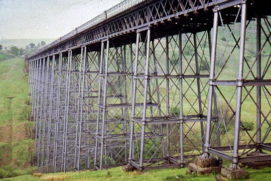
The Belah Viaduct consists of 15 piers of varying heights, according to the section of the valley, each pier being composed of six hollow columns, placed in the form of a tapering trapezium and firmly braced together with cross-girders at distances of 15 feet perpendicular, and by horizontal and diagonal wrought iron tie-bars.
The columns are 12 inches external diameter, and of varying thickness, from 1¼ inch to ⅞ inch, according to the height of the pier and their position in it. The columns are placed at distances of 50 feet centre to centre in the breadth of the pier at the base, and taper towards each other, until at the top, immediately under the platform girders, they are 22 feet apart from centre to centre.
The taper is given in the foundation piece at the base of each column, which foundation piece is firmly bolted to a stone base, the upper surface of which is bevelled at such an angle, as will produce the taper required for the columns. Thus the columns have all their flanges square to the centre line, which simplified the fitting very materially. The depth of the stone foundations varied according to the nature of the ground and the height of the piers, but in almost all cases they went down to the solid rock.
It is a distinguishing feature in this viaduct, that the cross or distance girders of the piers encircle the columns which are turned up at that point, the girders being bored out to fit the turned part with great accuracy. No cement of any kind was used in the whole structure, and the piers when completed, and the vertical and horizontal wrought iron bracings keyed up, are nearly as rigid as though they were one solid piece.
The platform girders, or wrought iron superstructure, are of the lattice construction, and were tested with 1 ton on every lineal foot, under which weight they manifested scarcely any visible deflection. There are three girders to each span: two outside girders which are 5 feet 10½ inches deep, and one middle girder, of equal depth to the latter, being of course much stronger in the scantlings than the outside girders. These three girders were firmly stayed to each other by metal cross-bracings and wrought iron ties, and are crossed by baulks of timber dressed and squared to 12 x 9 inches, which overhang the outside girders about 2 feet 6 inches. These baulks are again crossed by 3 inch planks, and these planks covered by a good thickness of finely-broken stones. The rails are carried by longitudinal baulks the whole length of the viaduct; and guard rails are fixed on both sides, so as to render it nearly impossible for the wheels of an engine or carriage to get off the way. The whole is surmounted by an elegant hand-railing of cast iron in which the design of the viaduct is well maintained.
The weight of the whole viaduct is: cast iron – 776 tons; wrought iron – 598 tons; the superstructure contains 12,843 cubic feet of Memel timber.
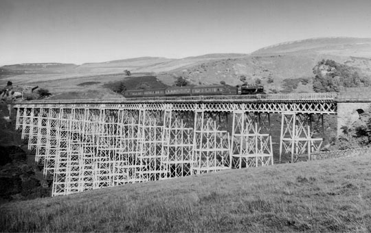
One important element which has to be provided for in these erections is that of expansion, which in such a length as the Belah – 1,000 feet – would become a serious difficulty if it were not arranged for. This Mr Bouch has done by the application of sliding plates lined with brass, on which every third girder rests, with liberty to move in its length within certain limits. The expansion of these girders which are secured together is thus provided for at one joint; and experience has proved that this is sufficient, as the girders move easily without producing the slightest effect on the piers. The total length of this viaduct is 1,000 feet, and the greatest depth from the rail to the ground 195 feet.
The two prominent and distinctive features of this class of railway viaducts are their cheapness and the rapidity with which they can be erected, the latter point being often of vital importance, as it not infrequently happens that a wide gorge becomes the key to a whole line of railway, and the power of bridging it rapidly may convert the capital of the railway, which would otherwise lie dormant, into active and remunerative stock.
No example could better illustrate this than the Belah viaduct, which was erected in the incredibly short space of four months by Messrs Gilkes Wilson and Co of Middlesbrough-on-Tees. A stone viaduct over the same spot would have occupied three years in its erection. Much of this quickness was, however, attained by the admirable arrangements made by this firm for the fitting and erection of the work. The fitting was all done by machines, which were specially designed for the purpose, and finished the work with mathematical accuracy.
The flanges of the columns were all faced up and their edges turned, and every column was stepped into the one below it with a lip about ⅝ of an inch in depth, the lip and the socket for it being accurately turned and bored. That portion of the column against which the cross-girders rested was also turned. The whole of these operations were performed at one time, the column being centred in a hollow mandril lathe. After being turned, the columns passed on to a drilling machine, in which all the holes in each flange were drilled out of the solid simultaneously. And as this was done with them all in the same machine, the holes of course perfectly coincided when the columns were placed one on the other in the progress of the erection. Similar care was taken with the cross girders which were bored out at the ends by machines designed for that purpose. Thus, when the pieces of the viaduct had to be put together at the place of erection, there was literally not a tool required, and neither chipping nor filing to retard the progress of the work.
The mode of erection adopted by Messrs Gilkes Wilson and Co was novel, but remarkably successful. They used no scaffold, but having prepared a crane, with a gib of sufficient length to reach from theabutment over the first pier, and, of course, from the first pier over the second, and so on, they commenced the erection by setting the first pier from the abutment, on the Brough side of the valley. The crane was balanced by a shifting weight box so that each piece of the pier, whether light or heavy, was counterbalanced as it swung; and they were thus enabled to lower it slowly and steadily to its place, whilst it was swinging round from the point of its first suspension. As soon as the first pier was erected, they placed two baulks across from the abutment to the pier, and ran the girder (which was placed on two low bogie wagons) over, dropping it into its place with the assistance of the crane, by which each end of each girder was lifted and lowered.
On the completion of the first span the crane was moved forward, and the erection of the second pier was commenced; and this process was pursued with singular success, not a single accident occurring during the whole erection, and not a man receiving any injury – a fact almost without parallel in the annals of railway engineering.
Some planks were placed upon the cross girders, which, with some hand ladders, enabled the workmen to go up and down readily. In the erection of this important work there were about 180 men engaged, and, as we have before stated, the whole was completed in a most expeditious manner.
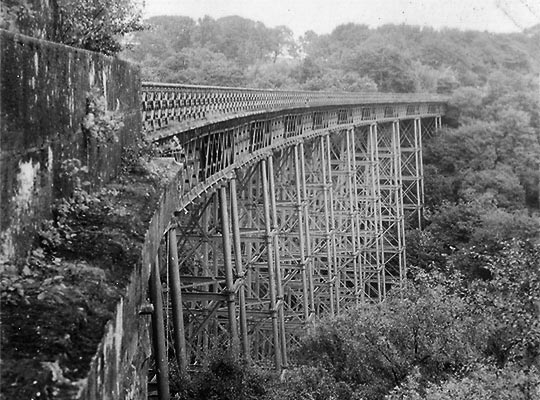
The Deepdale Viaduct is, in its details, identical with the Belah, all the piers and other parts being similar; but the Deepdale Viaduct is built upon a curve. The wrought iron work in these structures cost £22 per ton, and the cast iron work £11 per ton.
| Belah Viaduct: estimate of work (excluding masonry) | tons | cwts | qrs | lbs |
| Piers: wrought iron work | ||||
| Bar iron in tie bars and clip plates | 84 | 18 | 0 | 0 |
| Bolts, nuts, gibs and cotters | 21 | 3 | 0 | 0 |
| Cast iron work | ||||
| 510 columns and 78 foundation pieces | 353 | 4 | 0 | 0 |
| 738 girders | 308 | 16 | 2 | 0 |
| Superstructure: wrought iron work | ||||
| 42 main girders | 224 | 3 | 2 | 0 |
| 29 horizontal and transverse bracing | 34 | 18 | 2 | 0 |
| Bolts and spikes to platform | 2 | 5 | 0 | 0 |
| Cast iron work | ||||
| Bearings and brackets | 8 | 2 | 0 | 0 |
| Railing (552 yards lineal) at 1 cwt | 27 | 12 | 0 | 0 |
| Brass | ||||
| In sliding bearings | 0 | 2 | 2 | 0 |
| Timber | ||||
| Fir, bearers and planking | 9,815 cubic feet | |||
| Oak, bearings | 15 cubic feet |
| Deepdale Viaduct: estimate of work (excluding masonry) | tons | cwts | qrs | lbs |
| Piers: wrought iron work | ||||
| Bar iron in tie bars and clip plates | 64 | 6 | 1 | 14 |
| Bolts, nuts, gibs and cotters | 13 | 13 | 1 | 14 |
| Cast iron work | ||||
| 408 columns and 60 foundation pieces | 277 | 12 | 0 | 0 |
| Girders | 248 | 2 | 0 | 0 |
| Superstructure: wrought iron work | ||||
| Main girders | 176 | 2 | 3 | 0 |
| Horizontal and transverse bracing | 27 | 9 | 1 | 0 |
| Bolts and spikes to platform | 1 | 15 | 0 | 0 |
| Cast iron work | ||||
| Bearings and brackets | 6 | 8 | 0 | 0 |
| Railing (432 yards lineal) at 1 cwt | 21 | 12 | 0 | 0 |
| Brass | ||||
| In sliding bearings | 0 | 2 | 0 | 0 |
| Timber | ||||
| Fir, bearers and planking | 7,712 cubic feet | |||
| Oak, bearings | 12 cubic feet |
More Information
| Don’t Look Down | Nigel Carmichael recalls his work on Belah Viaduct |
| Stainmore 150 | An overview of the route’s viaducts |
